Claas Quantum 6800-4500 Gt P (615) Loader Wagon Technical System FR
$300.00
- Model: Quantum 6800-4500 Gt P (615) Loader Wagon
- Type Of Manual: Technical System
- Language: FR
- Format: PDF(s)
- Size: 16.9 MB
File List:
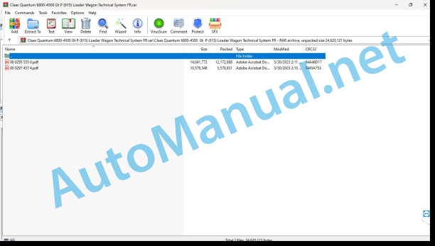
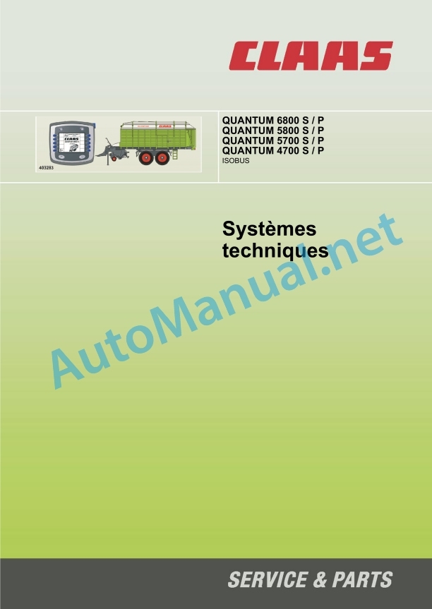
00 0295 555 0.pdf
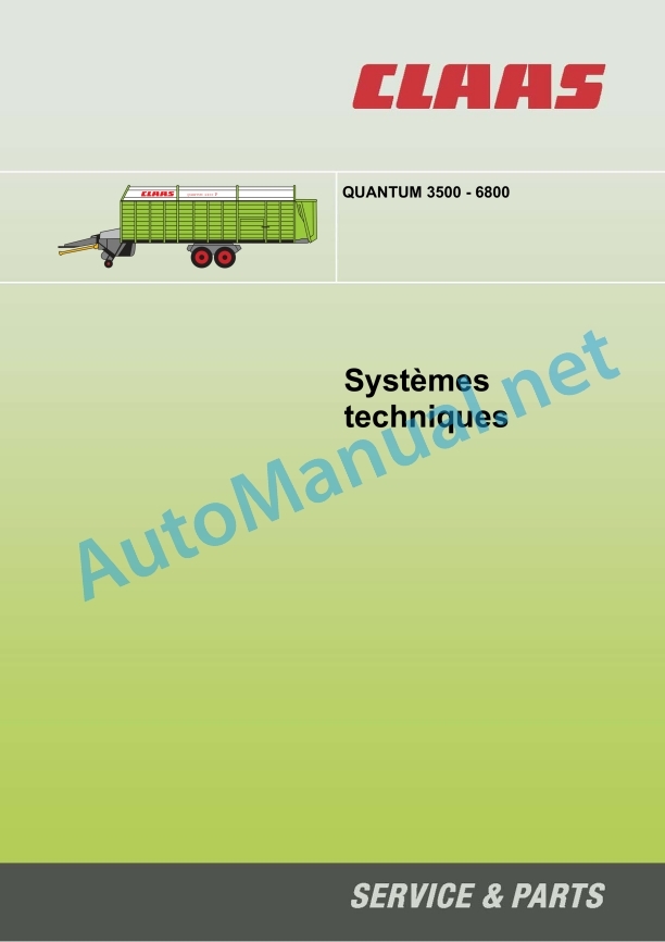
00 0297 457 4.pdf
00 0295 555 0.pdf:
Contents
1 Complete hydraulic system
Hydraulic principle diagram QUANTUM 6800 S – 4700 S
Overall principle diagram
Designations
Hydraulic principle diagram QUANTUM 6800 P – 4700 P
Complete connection diagram
Designations
Main valve block QUANTUM 6800 – 4700 S
QUANTUM 6800 – 4700 P main valve block
Designations
Location of hydraulic components
Components
2 Electrical equipment
Electrical diagram
Graphic (DIN A3)
Designations
Self-loading trailer module A108
Representation
Connector Allocation
Module A108 – self-loading trailer
Cutting chamber bottom position sensor (B067)
Representation
Function
Measurement value table
PTO shaft speed sensor rear (B142)
Representation
Function
Measurement value table
Traction force sensor (B144)
Representation
Function
Measurement value table
Rear hatch opening angle sensor (B206)
Representation
Function
Measurement value table
Pickup position sensor (B263)
Representation
Function
Measurement value table
Drawbar position sensor (B264)
Representation
Function
Measurement value table
Roof level fill sensor (B265)
Representation
Function
Measurement value table
100% Fill Level Indicator Sensor (B266)
Representation
Function
Measurement value table
Dosing roller speed sensor (B267)
Representation
Function
Measurement value table
Crop Fill Level Sensor (B268)
Representation
Function
Measurement value table
Alphabetical index
00 0297 457 4.pdf:
Technical systems – QUANTUM 3500 – 6800
1.0 Technical characteristics
1.0 QUANTUM 2500K, 2500P, 3500K, 3500P, 3800K, 3800P 2
1.1 QUANTUM 3500K, 3500P, 3500S, 3800K, 3800P, 2500K, 2500P
1.2 QUANTUM 5500 S-18, 5500 S-16, 5500 S, 4500 S, 6800 S
1.3 QUANTUM 6800 P, 6500 P, 5500 P-18, 5500 GT, 5500 P, 4500 P
1.0 QUANTUM 2500K, 2500P, 3500K, 3800K, 3800P, 3500S
1.1 Condensed user manual for the control panel
2.0 QUANTUM 4500S / 5500S / S-16 / S-18 / 6800S
2.1 Condensed user manual for the control panel
3.0 QUANTUM 4500P / 5500P / 5500P-16 / 5500P-18 / 5500GT / 6800P
3.1 Condensed user manual for the control panel
10.0 Pneumatic brake system
1.0 Pneumatic control plans
1.1 QUANTUM 5500P/S-16 40km/h, 16to, (steering axle)
1.2 QUANTUM 2500 K/P, 3500P/S/K, 3800K/P, 4500S/P 40km/h (Steering axle)
1.3 5500P/S 40km/h, 13to, (Steering axle)
1.4 5500P-18/S -18, 60km/h
1.5 5500P/S 80km/h (ABS)
1.6 Air suspension with level adjustment valve
1.7 5500 P/S 50/60 km/h
1.8 5500 S, 40/60 km/h
2.0 Settings
2.1 Diaphragm cylinder
2.2 Adjusting the linkage adjuster
2.3 Brake force regulator (ALD)
2.4 Air suspension
11.0 Hydraulic system
1.0 LS pump
1.1 Output position (Engine stopped)
1.2 Low pressure standby
1.3 A distributor activates = the LS pump switches to power supply
1.4 Constant flow
1.5 The pump limits the flow
1.6 Maximum pressure limitation (DBV function)
1.7 Hitch the self-loader (hydraulic power supply)
2.0 QUANTUM 3500K / 3800K / 3500P / 3500S
2.1 3500K, 2500K, 3800K
2.2 3500P, 2500P, 3800P
2.3 3500S
3.0 QUANTUM 4500S / 5500S / S-16 / S-18 / 6800S
3.1 Synoptic table
3.2 Order plan
3.3 Command block
3.4 4/3 distributor (cutting frame, raising/lowering of the articulated drawbar)
3.5 3/3 distributor (opening/closing of the rear hatch)
3.6 Valve block (Pick-up and metering rollers)
3.7 Hydraulic cylinder for activating the pick-up and dosing rollers
3.8 DANFOSS OMR 125 hydraulic motor for moving floor (single bearing motor)
3.9 2-speed motor
3.10 3-way flow limiter Cross conveyor
3.11 Distributor 4/3 (Cross conveyor)
3.12 3/2 distributor (cross conveyor) QUANTUM S
4.0 QUANTUM 4500P / 5500P / 5500 P-16 / 5500 P-18 / 5500GT / 6500P / 6800P
4.1 Order plan
4.2 Function
4.3 Circuit valve with pressure limiter
4.4 Proportional distributor 4/3
4.5 Distributor 4/3
4.6 2/2 distributor (seat valve)
4.7 DANFOSS OMR 125 hydraulic motor
4.8 Failure and their solutions
4.9 Stop cylinder for flywheel axle
5.0 QUANTUM 6800
5.1 Forced steering
12.0 Electrical system
1.0 QUANTUM 2500K, 2500P, 3500K, 3500P, 3500S, 3800K, 3800P
1.1 Control plan 3500 K, 3800 K, 2500 K
1.2 Order plan 3800 P, 3500 P, 2500 P
1.3 3500 S order plan
1.4 SC-2000-U Amplifier
1.5 Lighting
2.0 QUANTUM 4500S / 5500S / S-16 / S-18 / 6800S
2.1 Order plan
2.2 Diagnostic system
2.3 QUANTUM S power board (A)
2.4 Setting the reed switch
2.5 Dip switch
2.6 QUANTUM S lighting
3.0 QUANTUM 4500P / 5500P / 5500P-16 / 5500P-18 / 5500GT / 6500P / 6800P
3.1 Order plan
3.2 QUANTUM P Dispenser cabinet
3.3 Faults and solutions
3.4 QUANTUM P Lighting
0297 457.4
John Deere Repair Technical Manual PDF
John Deere Diesel Engines POWERTECH 2.9 L Component Technical Manual CTM126 Spanish
John Deere Repair Technical Manual PDF
John Deere Repair Technical Manual PDF
John Deere POWERTECH E 4.5 and 6.8 L Diesel Engines TECHNICAL MANUAL 25JAN08
John Deere Parts Catalog PDF
John Deere Harvesters 8500 and 8700 Parts Catalog CPCQ24910 Spanish
John Deere Repair Technical Manual PDF
John Deere Repair Technical Manual PDF
John Deere Repair Technical Manual PDF
John Deere Diesel Engines PowerTech 4.5L and 6.8L – Motor Base Technical Manual 07MAY08 Portuguese
John Deere Repair Technical Manual PDF
John Deere Repair Technical Manual PDF
John Deere 18-Speed PST Repair Manual Component Technical Manual CTM168 10DEC07


