


Komatsu Operation and Maintenance Manual PDF
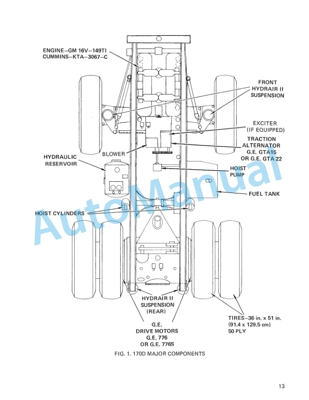
Komatsu 170D Dump Truck Operation and Maintenance Manual DG534
Komatsu Operation and Maintenance Manual PDF
Komatsu 210M Dump Truck Operation and Maintenance Manual DG692
Komatsu Operation and Maintenance Manual PDF
Komatsu 730E Dump Truck Operation and Maintenance Manual CEAM020001
Komatsu Operation and Maintenance Manual PDF
Komatsu 730E Dump Truck Operation and Maintenance Manual CEAM011200

Komatsu Operation and Maintenance Manual PDF
Komatsu 210M Dump Truck Operation and Maintenance Manual DG615
Komatsu Operation and Maintenance Manual PDF
Komatsu Operation and Maintenance Manual PDF
Komatsu 101 Basics Forklift Truck Operation and Maintenance Manual
Komatsu Operation and Maintenance Manual PDF
Komatsu 410W Hydraulic Excavator Operation and Maintenance Manual UMGB410W1
Komatsu Operation and Maintenance Manual PDF
Komatsu 4D104E, S4D104E Series Diesel Motor Operation and Maintenance Manual WHBMNEF000