Komatsu PC950-11, PC950LC-11 Hydraulic Excavator Field Assembly Manual GEN00268-01
$20.00
- Type Of Manual: Field Assembly Manual
- Manual ID: GEN00268-01
- Format: PDF
- Size: 20.4MB
- Number of Pages: 205
-
Model List:
- PC950-11 Hydraulic Excavator
- PC950LC-11 Hydraulic Excavator
- 1. Cover
- 1.1. FOREWORD
- 1.2. CONTENTS
- 1.3. SAFETY INFORMATION
- 1.3.1. SAFETY NOTICE FOR OPERATION
- 1.3.2. PRECAUTIONS TO PREVENT FIRE
- 1.3.3. ACTIONS IF FIRE OCCURS
- 1.3.4. PRECAUTIONS FOR DISPOSING OF WASTE MATERIALS
- 1.3.5. ACTIONS TAKEN TO MEET EXHAUST GAS REGULATIONS
- 1.3.6. PRECAUTIONS FOR DEF
- 1.3.7. STORE AdBlue/DEF
- 1.3.8. PRECAUTIONS FOR HANDLING HYDRAULIC EQUIPMENT
- 1.3.9. PRECAUTIONS FOR DISCONNECTION AND CONNECTION OF PIPINGS
- 1.3.10. PRECAUTIONS FOR HANDLING ELECTRICAL EQUIPMENT
- 1.3.11. PRECAUTIONS FOR HANDLING FUEL SYSTEM EQUIPMENT
- 1.4. HANDLING OF TIEOFF ANCHOR POINTS
- 1.5. BE CAREFUL NOT TO HIT BUCKET WHEN RETRACTING WORK EQUIPMENT
- 1.6. SPECIFICATIONS
- 1.7. PRECAUTIONS FOR FIELD ASSEMBLY
- 1.8. DISPOSAL OF REMOVED PARTS
- 1.9. ASSEMBLY PROCEDURE, FACILITY USED, AND SCHEDULE
- 1.10. KIT LAYOUT DIAGRAM
- 1.11. FLOW OF MAIN FIELD ASSEMBLY
- 1.12. TRANSPORTATION PACKING STYLE
- 1.13. FIELD ASSEMBLY TOOLS LIST
- 1.14. TIGHTENING TORQUE
- 1.15. COATING MATERIALS
- 1.16. SELECTION OF WIRE ROPES USED FOR ASSEMBLY
- 1.17. SELECTION OF NYLON SLINGS USED FOR ASSEMBLY
- 1.18. ASSEMBLY OF CHASSIS
- 1.18.1. A1 Replacement of return filter (Standard > Flushing)
- 1.18.2. A2 Installation of R.H. and L.H. track frames
- 1.18.3. A3 Installation of travel piping (PC950)
- 1.18.4. A3 Installation of travel piping (PC950LC)
- 1.18.5. A4 Installation of step
- 1.18.6. A5 Sticking revolving frame sheets
- 1.18.7. A6 Installation of L.H. side step
- 1.18.8. A7 Installation of R.H. side step
- 1.18.9. A8 Installation of handrail
- 1.18.10. A9 Installation of R.H. rearview mirror
- 1.18.11. A10 Installation of L.H. rearview mirror
- 1.18.12. A11 Sticking counterweight sheets
- 1.18.13. A12 Assembly procedure of KomVision camera
- 1.18.14. A13 Installation of counterweight revolving lamp (if equipped)
- 1.18.15. A14 Installation of counterweight rear lamp
- 1.18.16. A15 Installation of counterweight
- 1.18.17. A16 Installation of cab top step lamp
- 1.18.18. A17 Installation of cab revolving lamp (if equipped)
- 1.18.19. A18 Bleed air from hydraulic pump
- 1.18.20. A19 Bleed air from travel motor
- 1.18.21. A20 Installation of travel piping covers (PC950)
- 1.18.22. A20 Installation of travel piping covers (PC950LC)
- 1.18.23. A21 Installation of track frame undercovers
- 1.18.24. A22 Installation of travel motor guards
- 1.18.25. A23 Adjustment of track tension
- 1.18.26. A24 Installation of fire extinguisher (if equipped)
- 1.18.27. A25 Installation of transportation jigs (muffler)
- 1.19. Assembly of work equipment
- 1.19.1. B1 Release pressure remaining in hydraulic circuit
- 1.19.2. B2 Installation of boom antidrop valve to boom cylinder
- 1.19.3. B3 Installation of boom cylinder to revolving frame
- 1.19.4. B4 Installation of boom antidrop valve hoses
- 1.19.5. B5 Installation of boom cylinder hoses
- 1.19.6. B6 Bleed air from cylinder
- 1.19.7. B7 Installation of dust seal to boom foot
- 1.19.8. B8 Installation of arm dust seal
- 1.19.9. B9 Installation of boom assembly
- 1.19.10. B10 Installation of boom hoses (between machine and boom)
- 1.19.11. B11 Installation of arm antidrop valve hoses (Between body and boom)
- 1.19.12. B12 Installation of boom cylinder
- 1.19.13. B13 Fixing of boom antidrop valve hoses
- 1.19.14. B14 Installation of arm assembly
- 1.19.15. B15 Installation of hoses between boom and bucket cylinder
- 1.19.16. B16 Installation of bucket assembly
- 1.19.17. B17 Clearance standard for installation of work equipment
- 1.19.18. B18 Installation of work equipment grease piping
- 1.19.19. B19 Installation of work equipment lamp wiring
- 1.19.20. B20 Greasing after assembling work equipment
- 1.20. Testing and maintenance procedures after completing assembly
- 1.20.1. M1 Check hydraulic tank oil level and add oil
- 1.20.2. M2 Flushing of hydraulic circuit
- 1.20.3. M3 Replacement of return filter (Flushing > Standard)
- 1.20.4. M4 Check of oil and coolant levels at each section
- 1.20.5. M5 Places to touch up after field assembly
- 1.20.6. M6 Setting of KomVision (Camera calibration)
- 1.20.7. M7 Inspection method of 12 m visibility (KomVision)
- 1.20.8. M8 Check display of failure code
- 1.20.9. M9 Installation of fuel tank oil filler lock
- 1.21. Field assembly inspection check sheet
Komatsu Operation and Maintenance Manual PDF
Komatsu 330M Dump Truck Operation and Maintenance Manual DG729
Komatsu Operation and Maintenance Manual PDF
Komatsu 730E Dump Truck Operation and Maintenance Manual CEAD014800
Komatsu Operation and Maintenance Manual PDF
Komatsu 410W Hydraulic Excavator Operation and Maintenance Manual UMGB410W1
Komatsu Operation and Maintenance Manual PDF
Komatsu 450FXL-1 Crawler Feller Buncher Operation and Maintenance Manual CEAM023802
Komatsu Operation and Maintenance Manual PDF
Komatsu 170D Dump Truck Operation and Maintenance Manual DG534
Komatsu Operation and Maintenance Manual PDF
Komatsu 530M Dump Truck Operation and Maintenance Manual DG716
Komatsu Operation and Maintenance Manual PDF
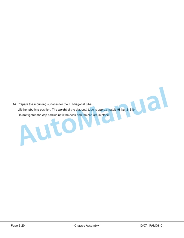
Komatsu 730E Dump Truck Field Assembly Instruction CEAW004103
Komatsu Operation and Maintenance Manual PDF
Komatsu 503 Motor Grader Operation and Maintenance Manual 2079A-H45
Komatsu Operation and Maintenance Manual PDF
Komatsu 730E Dump Truck Operation and Maintenance Manual CEAM011200
Komatsu Operation and Maintenance Manual PDF
Komatsu 730E Dump Truck Operation and Maintenance Manual CEAM018100