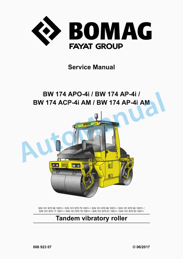
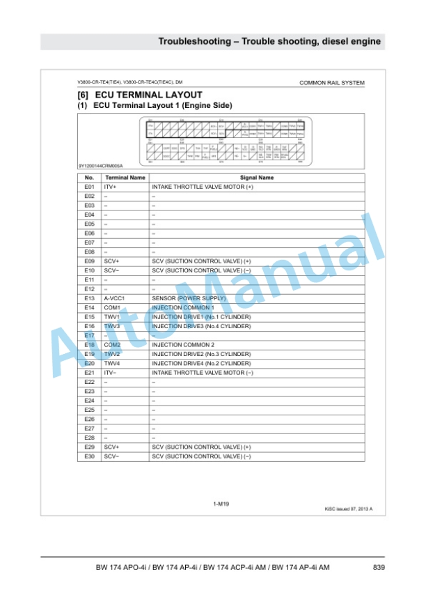
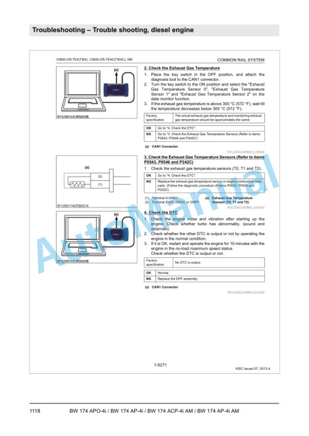
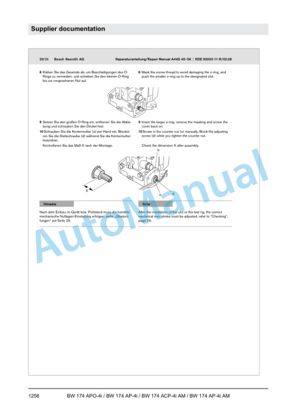
Bomag BW 174 APO-4i, BW 174 AP-4i, BW 174 ACP-4i AM, BW 174 AP-4i AM Tandem Vibratory Roller Service Manual 00892307
$30.00
- Type Of Manual: Service Manual
- Manual ID: 00892307
- Format: PDF
- Size: 105.2MB
- Number of Pages: 1676
- Serial Number:
101870561001 and up
101870751001 and up
101870901001 and up
101870921001 and up
101870171001 and up
101870761001 and up
101870911001 and up
101870931001 and up
Category: Bomag Service Manual PDF
-
Model List:
- BW 174 APO-4i Tandem Vibratory Roller
- BW 174 AP-4i Tandem Vibratory Roller
- BW 174 ACP-4i AM Tandem Vibratory Roller
- BW 174 AP-4i AM Tandem Vibratory Roller
- 1. Table of contents
- 2. General
- 2.1. Introduction
- 2.2. Concerning your safety
- 2.3. Notes on repair
- 2.4. Fuels and lubricants
- 2.5. List of fuels and lubricants, BW 174 AP4
- 2.6. List of fuels and lubricants, BW 174 APO4
- 2.7. List of fuels and lubricants, BW 174 AP4 AM
- 2.8. List of fuels and lubricants, BW 174 ACP4 AM
- 3. Technical data
- 3.1. BW 174 AP4
- 3.2. BW 174 APO4
- 3.3. BW 174 AP4 AM
- 3.4. BW 174 ACP4 AM
- 3.5. Additional technical data
- 4. Overview of machine
- 4.1. BOMAG pivot steered tandem rollers
- 4.2. Electric systems
- 4.3. Diesel engine
- 4.4. Hydraulic system
- 4.5. Air conditioning
- 4.6. AP drum
- 4.7. AM and APO drum
- 5. Electric systems
- 5.1. Overview of electric system
- 5.2. Table of fuels and lubricants
- 5.3. Wiring
- 5.4. MESX, A83
- 5.5. CAN BUS overview
- 5.6. Starting the engine with jump leads
- 5.7. Electric steering wheel, A45
- 5.8. Steering angle sensors, B65 B66
- 5.9. Proximity switches for seat position detection, B178 B179
- 5.10. Speed sensor, B60
- 5.11. Asphalt temperature sensor, B106
- 5.12. Acceleration transducer, B84 B85
- 5.13. Electric module, A108
- 5.14. Data collector, A80
- 5.15. Differential pressure switch on hydraulic oil filter (B21 B22)
- 5.16. Operators stand
- 5.17. Fuse assignment
- 5.18. Generator
- 5.19. Starter
- 5.20. Telemecanique switch
- 5.21. Deutsch plug, series DT and DTM
- 5.22. Inspection and maintenance work
- 6. Diesel engine
- 6.1. Overview of diesel engine
- 6.2. Features
- 6.3. Cooling system
- 6.4. Intake air heating
- 6.5. Fuel supply
- 6.6. CommonRail system
- 6.7. Exhaust system
- 6.8. Regeneration of exhaust gas aftertreatment system
- 6.9. Removing and installing the thermostat
- 6.10. Checking the thermostat in disassembled state
- 6.11. Inspection and maintenance work
- 7. Hydraulic system
- 7.1. Overview of hydraulics
- 7.2. Open and closed hydraulic circuit
- 7.3. Hydraulic units
- 7.4. Supply and charge circuit
- 7.5. Travel circuit
- 7.6. Vibration circuit
- 7.7. Steering and crabwalk
- 7.8. Edge cutter, AG6
- 7.9. Edge cutter, AG42
- 7.10. Chip spreader
- 7.11. Test and adjustment points
- 7.12. Tests and adjustments
- 7.13. Flushing and bleeding
- 7.14. Inspection and maintenance work
- 8. ASPHALT MANAGER
- 8.1. Controlled compaction
- 8.2. Description of function
- 8.3. Automatic measuring and controlling
- 8.4. MESX, A83
- 8.5. Block diagrams
- 8.6. Asphalt temperature sensor, B106
- 8.7. Acceleration transducer, B84 B85
- 8.8. Speed sensor, B60
- 8.9. Hydraulic circuit
- 8.10. Replacing the slewing motor
- 8.11. Potentiometer on slewing motor, B97
- 8.12. Drum
- 8.13. Inspection and maintenance work
- 9. Air conditioning
- 9.1. Overview of air conditioning system
- 9.2. Physical principles
- 9.3. Refrigerant R134a
- 9.4. Compressor oil / refrigeration oil
- 9.5. Working principle of the air conditioning system
- 9.6. Monitoring devices
- 9.7. Description of components
- 9.8. Compressor
- 9.9. Emptying in case of repair
- 9.10. Drying and evacuation
- 9.11. Filling instructions
- 9.12. Steam table for R134a
- 9.13. Inspection and maintenance work
- 10. Drum
- 10.1. Overview, AP drum
- 10.2. Removing the AP drum
- 10.3. Dismantling the AP drum
- 10.4. AD/AP Removing, assembling the exciter unit
- 10.5. Assembling the AP drum
- 10.6. Installing the AP drum
- 10.7. Repair overview AM/APO drum
- 10.8. Removing the AM/APO drum
- 10.9. Dismantling the AM/APO drum
- 10.10. Assembling the AM/APO drum
- 10.11. Installing the AM/APO drum
- 10.12. Inspection and maintenance work AP, AM and ACP AM
- 10.13. Inspection and maintenance work, ACP AM
- 11. Pivot steering
- 11.1. Repair overview oscillating/pivot steering
- 11.2. Removing the oscillating/pivot steering
- 11.3. Installing the oscillating/pivot steering
- 11.4. Repair overview pivot steering
- 11.5. Removing the pivot steering
- 11.6. Installing the pivot steering
- 11.7. Inspection and maintenance work
- 12. Precision spreader
- 12.1. Mounting / removing the precision spreader
- 12.2. Inspection and maintenance work
- 13. Troubleshooting
- 13.1. Preliminary remarks
- 13.2. Emergency procedures
- 13.3. Troubleshooting, electrical systems
- 13.4. Trouble shooting, diesel engine
- 13.5. Trouble shooting, hydraulics
- 13.6. Trouble shooting, air conditioning system
- 14. Special tools
- 14.1. Special tools, electrics
- 14.2. Special tools, hydraulic system
- 14.3. Special tools, drum
- 14.4. List of special tools
- 15. Index
- 16. Appendix
- 16.1. A Supplier documentation
- 16.2. B Circuit diagrams
Rate this product
You may also like
Bomag Service Manual PDF
$30.00
Bomag Service Manual PDF
$30.00
Bomag Service Manual PDF
$30.00
Bomag Service Manual PDF
Bomag BC 572 RB Refuse Compactor Electric, Hydraulic Schematics Diagram 101570631001 – 101570631163
$30.00
Bomag Service Manual PDF
Bomag BC 571 RB Refuse Compactor Electric, Hydraulic Schematics Diagram 101570621033 – 101570621062
$30.00
Bomag Service Manual PDF
$30.00
Bomag Service Manual PDF
$30.00
Bomag Service Manual PDF
Bomag BC 472 RB Refuse Compactor Electric, Hydraulic Schematics Diagram 101930041001 – 101930041022
$30.00
Bomag Service Manual PDF
Bomag BC 472 RS Refuse Compactor Electric, Hydraulic Schematics Diagram 101930011002 – 101930011011
$30.00
Bomag Service Manual PDF
$30.00

