


Bomag BW 190 AD-5, BW 202 AD-5, BW 190 ADO-5, BW 202 ADO-5 Tandem Vibratory Roller Service Manual 00892592
$30.00
- Type Of Manual: Service Manual
- Manual ID: 00892592
- Format: PDF
- Size: 71.5MB
- Number of Pages: 874
- Serial Number:
101921121001 and up
101921421001 and up
101921111001 and up
101921411001 and up
101921311001 and up
101921491001 and up
101921321001 and up
101921481001 and up
Bomag Service Manual PDF
Bomag BC 472 RS Refuse Compactor Electric, Hydraulic Schematics Diagram 101930051001 – 101930051010

Bomag Service Manual PDF
Bomag BC 462 EB Refuse Compactor Electric, Hydraulic Schematics Diagram 101930021001 – 101930021018
Bomag Service Manual PDF
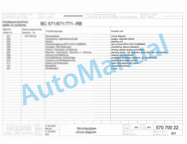
Bomag BC 571 RB Refuse Compactor Electric, Hydraulic Schematics Diagram 101570621033 – 101570621062

Bomag Service Manual PDF
Bomag Service Manual PDF
Bomag Service Manual PDF

Bomag Service Manual PDF
Bomag BC 462 EB Refuse Compactor Electric, Hydraulic Schematics Diagram 101930061001 – 101930061001
Bomag Service Manual PDF
Bomag Service Manual PDF
Bomag Service Manual PDF
Bomag BC 473 EB-3 Refuse Compactor Electric Schematics Diagram 101930151001 – 101930159999