


Bomag BW 211 D-40 to BW 213 PD-40 Single Drum Roller Service Manual 00840190
$30.00
- Type Of Manual: Service Manual
- Manual ID: 00840190
- Format: PDF
- Size: 111.7MB
- Number of Pages: 1392
- Serial Number:
101583481095 and up
861583551001 and up
861583561001 and up
101582421940 and up
101582432399 and up
101582441209 and up
101582471053 and up
101582481239 and up
101582491019 and up
Bomag Service Manual PDF
$30.00
Bomag Service Manual PDF
$30.00
Bomag Service Manual PDF
$30.00
Bomag Service Manual PDF
Bomag BC 472 RS Refuse Compactor Electric, Hydraulic Schematics Diagram 101930051001 – 101930051010
$30.00
Bomag Service Manual PDF
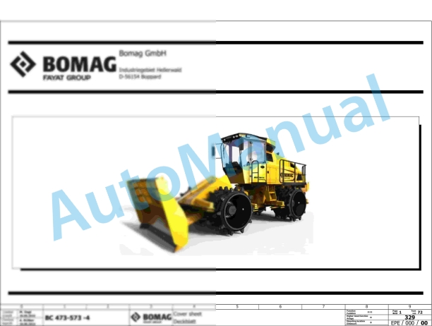
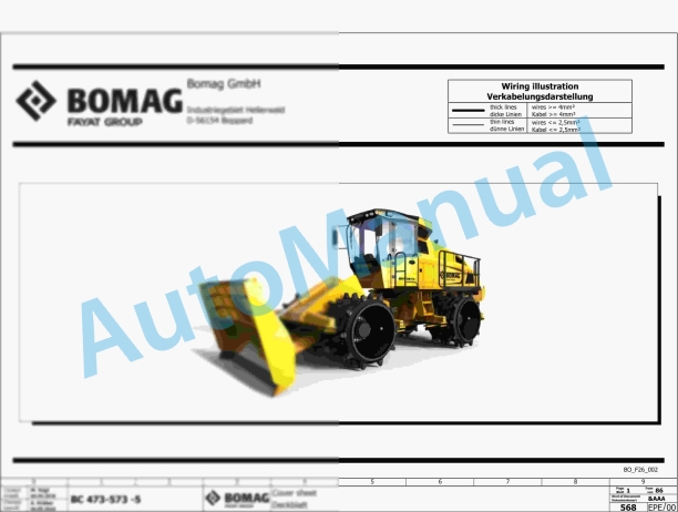
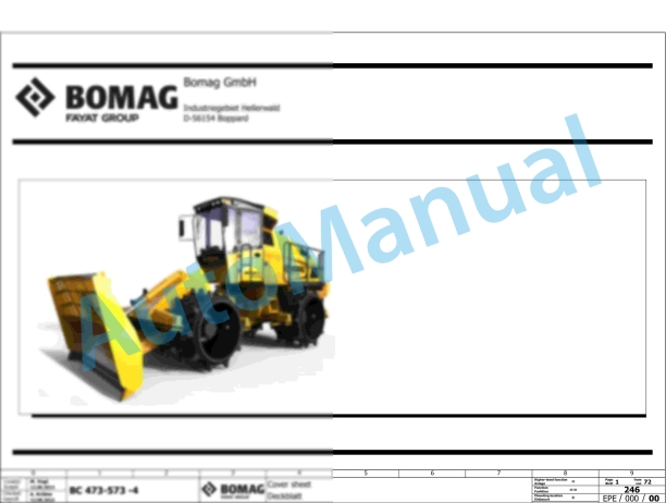
Bomag BC 473 EB-3 Refuse Compactor Electric Schematics Diagram 101930151001 – 101930159999
$30.00
Bomag Service Manual PDF
$30.00

Bomag Service Manual PDF
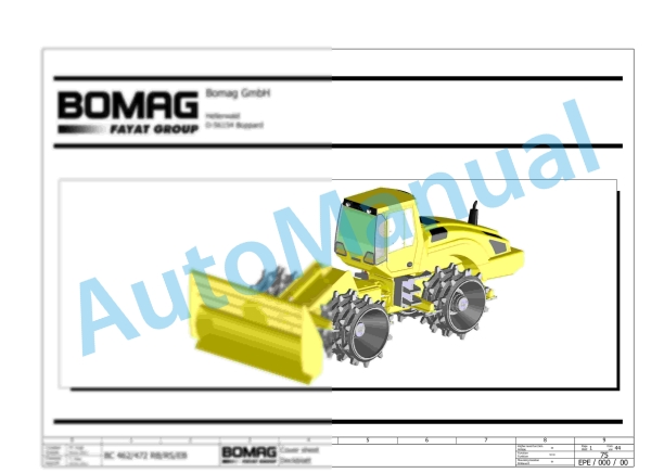
Bomag BC 462 EB Refuse Compactor Electric, Hydraulic Schematics Diagram 101930021001 – 101930021018
$30.00
Bomag Service Manual PDF
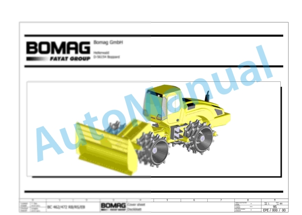
Bomag BC 462 RB Refuse Compactor Electric, Hydraulic Schematics Diagram 101930071001 – 101930071002
$30.00

Bomag Service Manual PDF
$30.00
Bomag Service Manual PDF
$30.00