


Yanmar Operator Manual PDF
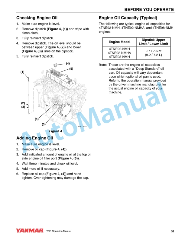
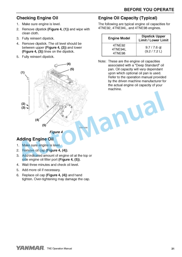
Yanmar 4TNE92, 4TNE94L, 4TNE98 Industrial Engine Operation Manual 0ATNE-G00100
$20.00
Yanmar Operator Manual PDF
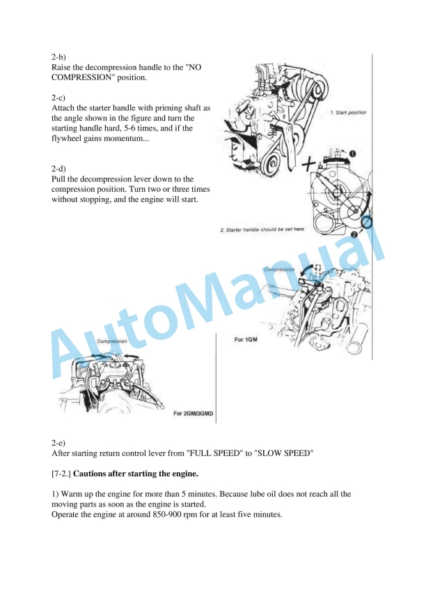
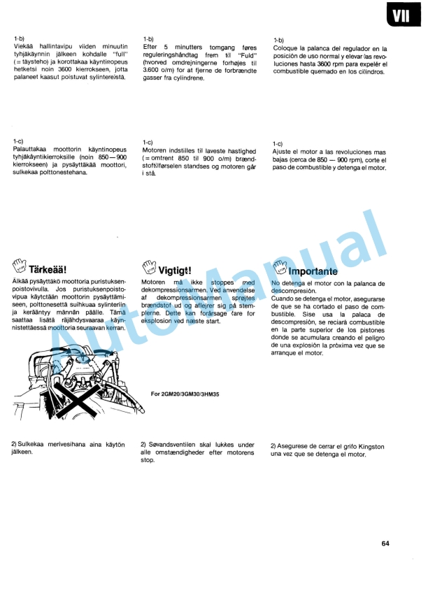
Yanmar 1GM10, 2GM20(F), 3GM30(F), 3HM35(F) Engine Operation Manual
$20.00
Yanmar Operator Manual PDF
Yanmar 2TNV70 to 4TNV106T Industrial Engine Operation Manual 0ATNV-G00101
$20.00
Yanmar Operator Manual PDF
Yanmar 2TNV70 to 4TNV106T Industrial Engine Operation Manual 0ATNV-G00100
$20.00
,%203GM30(F),%203HM35(F)%20Engine%20Operation%20Manual&url=https://automanual.net/doc/yanmar-1gm10-2gm20f-3gm30f-3hm35f-engine-operation-manual/&media=https://automanual.net/wp-content/uploads/2026/01/yanmar-1gm10-2gm20f-3gm30f-3hm35f-engine-operation-manual-1.jpg)