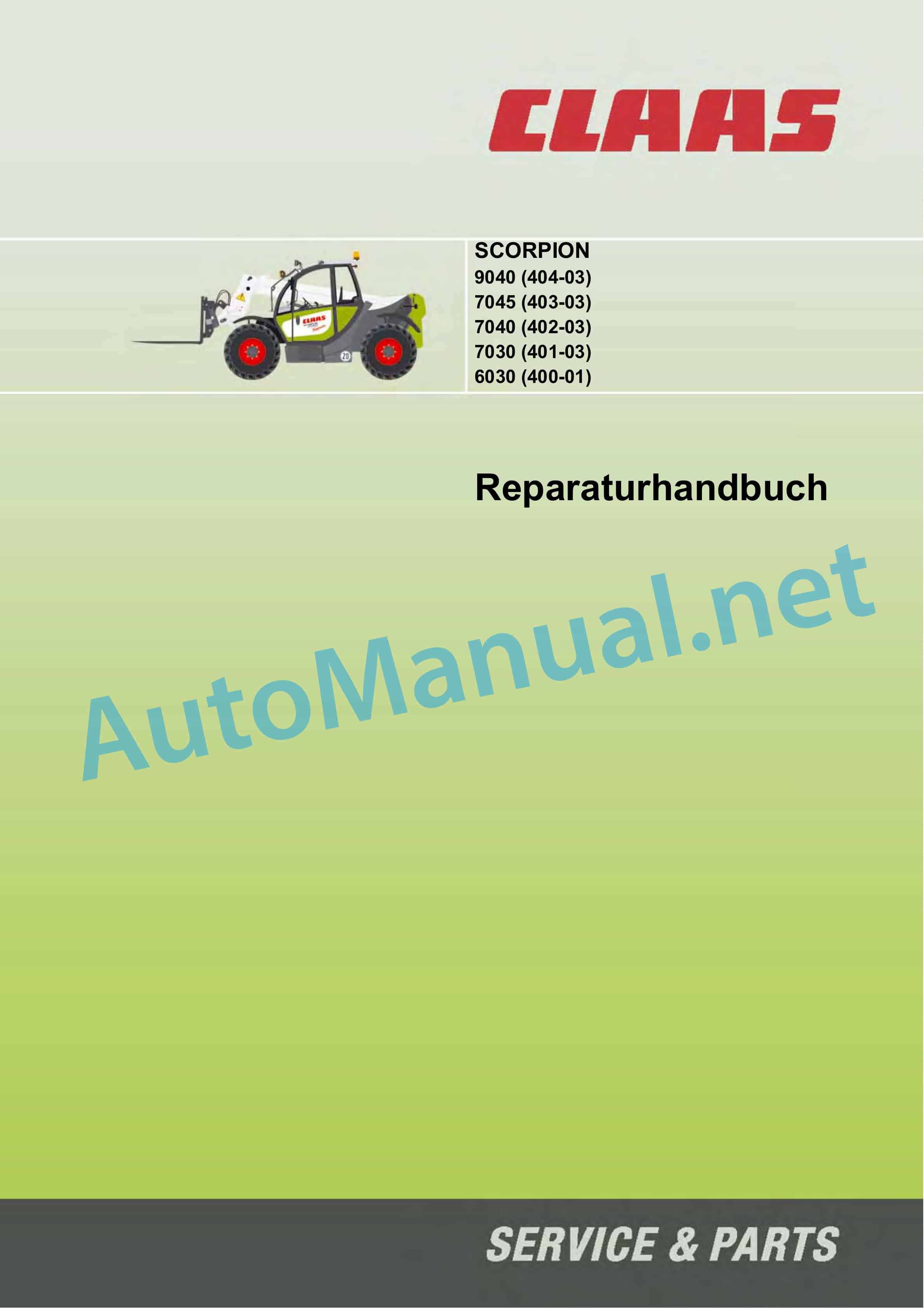
Claas SCORPION 7030 (K12) Telehandlers Repair Manual DE
$300.00
- Model: SCORPION 7030 (K12) Telehandlers
- Type Of Manual: Repair Manual
- Language: DE
- Format: PDF(s)
- Size: 213 MB
File List:
– 00 0295 724 2.pdf
– 00 0300 134 0.pdf
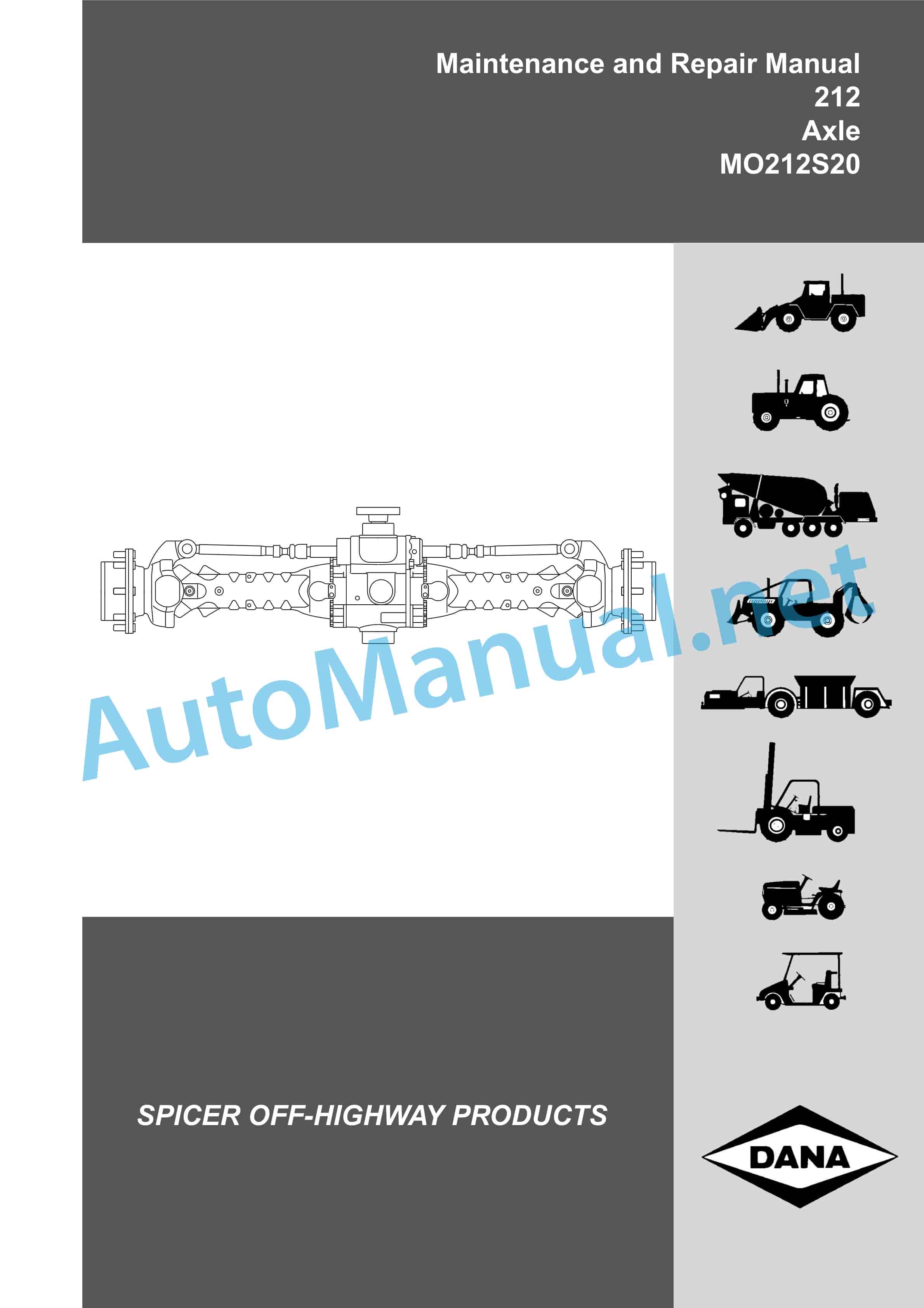
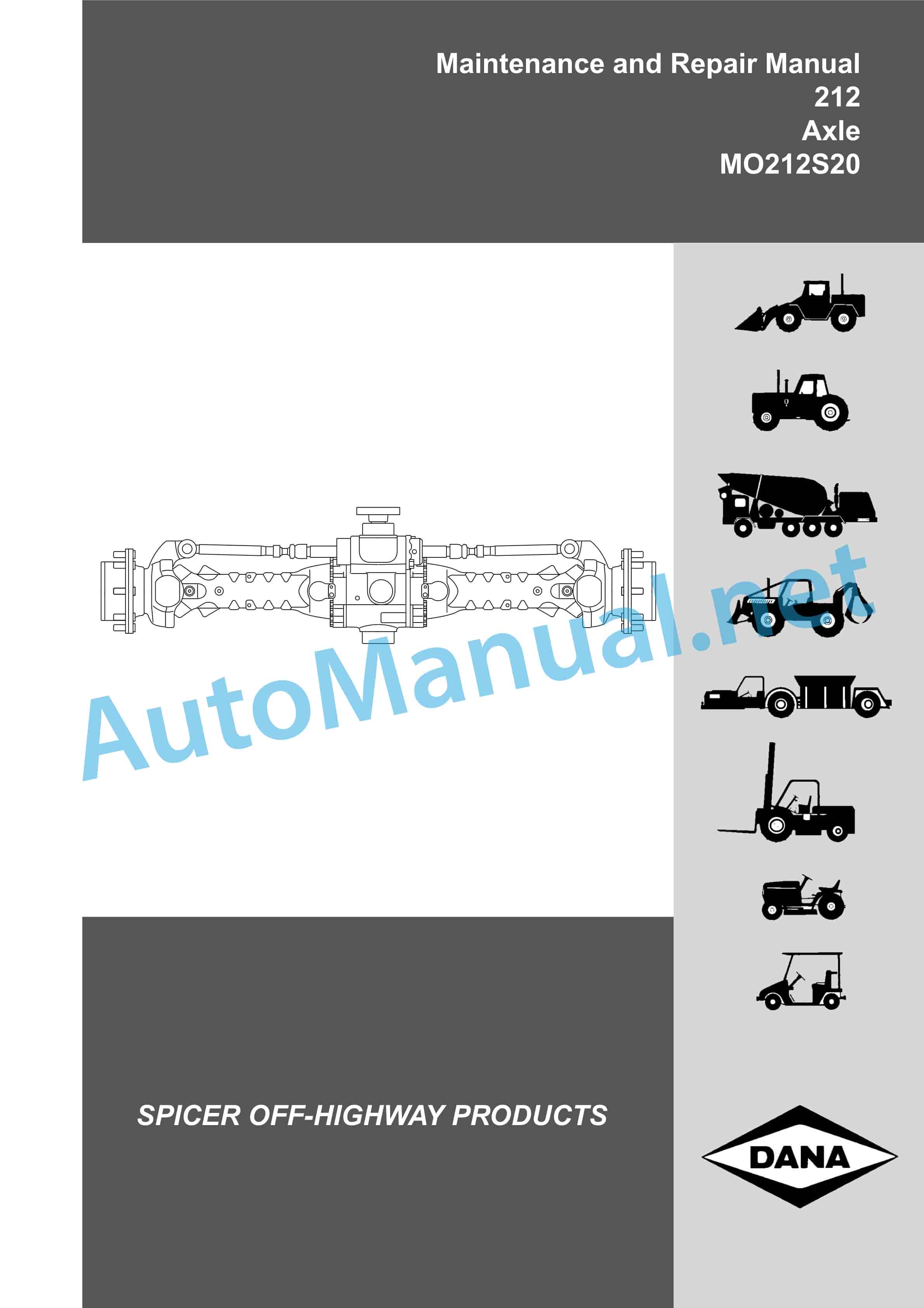
– 212 Axle MO212S20.pdf
– Axle MO212S20.pdf
– DEUTZ 2012.pdf
– DEUTZ TD TCD 2012 2V common rail injection.pdf
– DEUTZ TD TCD 2012 2V Mechanical Injection.pdf
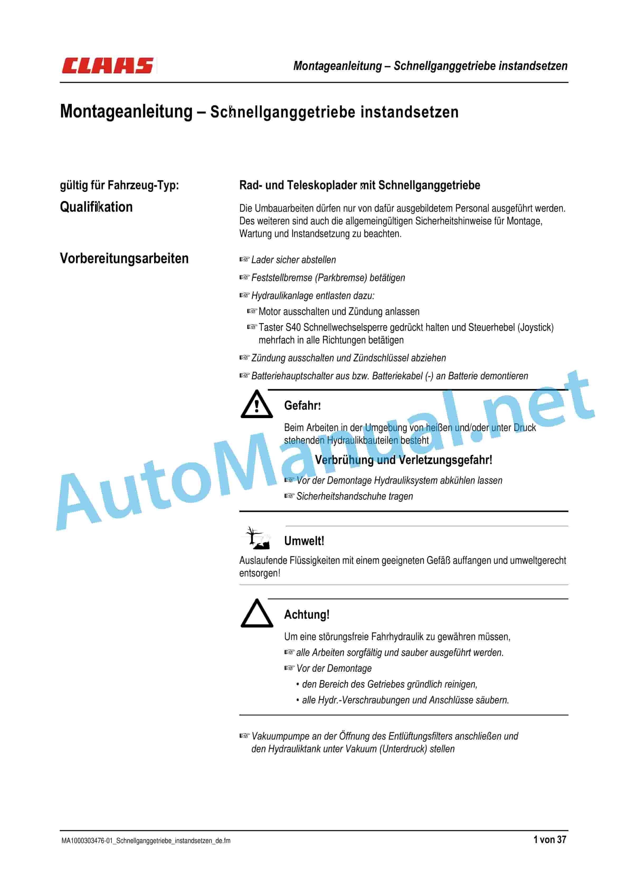
– SCORPION Repairing the high-speed gearbox.pdf
00 0295 724 2.pdf
Table of Content:
1 Repair manual
1.1 1 Overview: vehicle, use, operation
1.2 2 Technical data
1.3 3 Maintenance and care work
1.4 4 Motor
1.5 5 travel drive
1.6 6 axles – differential lock
1.7 7 Brake
1.8 8 Steering
1.9 9 Working hydraulics
1.10 10 Electrical systems
1.11 A Appendix
00 0300 134 0.pdf
Table of Content:
1 MA conversion of control unit from 5310 to HDS34
1.1 Qualification
1.2 Required tools
1.3 Control unit replaced by:
1.4 Pictures: Dismantling existing control unit
1.5 Pictures: Top control unit (screw connections installed)
1.6 Pictures: Top control unit (hosed)
1.7 Pictures: Top control unit (hosed)
1.8 Mounting the control unit underside (version: hydraulic connection at the rear)
1.9 Mounting the control unit underside
1.10 Preparation for assembly
1.11 Dismantling: Control unit
1.12 Assembly: Control unit
1.13 Commissioning
2 Assembly instructions for replacing a 5310 control by an HDS34 control valve
2.1 Qualification
2.2 Necessary tools
2.3 Control valve replaced by:
2.4 Figures: removing the existing control valve
2.5 Figures: control valve top side (screw connections fitted)
2.6 Figures: control valve top side (hoses fitted)
2.7 Figures: control valve top side (hoses fitted)
2.8 Control valve assembly, lower side (rear hydraulic port version)
2.9 Assembly, control valve lower side
2.10 Preparatory work
2.11 Removing the control valve
2.12 Installing the control valve
2.13 Putting into operation
3 assembly instructions for replacing the 5310 distributor for the HDS34 distributor
3.1 Qualification
3.2 Necessary tools
3.3 Distributor remplac par :
3.4 Figures: dpose du distributeur existing
3.5 Figures : face superieure du distributeur (vissages monts)
3.6 Figures : face superieure du distributeur (flexibles installs)
3.7 Figures : face superieure du distributeur (flexibles installs)
3.8 Montage du distributeur, face infrieure (version : raccord hydraulique AR)
3.9 Assembly, lower face of the distributeur
3.10 Travaux prparatoires
3.11 Dpose du distributeur
3.12 Monter le distributeur
3.13 Mise en marche
DEUTZ 2012.pdf
Table of Content:
1 Unnamed Adjust valve clearance
6 Removing and installing rocker arms and rocker arm bracket
7 Disassemble and complete the rocker arm and rocker arm bracket, check
8 Removing and installing cylinder head
9 Measure piston protrusion
Removing and installing 10 valves
11 Check valves
12 Check valve guide
13 Check valve residue
14 Check crankshaft axial play
15 Check crankshaft
16 Replace crankshaft seal (flywheel side)
17 Replace crankshaft seal (opposite flywheel side)
18 Check connecting rod
19 Removing and installing crankshaft
20 Remove and install mass balance shafts, check
21 Removing and installing piston and connecting rod
22 Check piston
23 Check piston rings and piston ring grooves
Removing and installing 24 piston cooling nozzles
25 Removing and installing crankcase ventilation
Check 26 cylinders
27 Removing and installing the front cover (opposite flywheel side)
28 Removing and installing connection housing
29 Removing and installing camshaft bearings, checking
30 Removing and installing the gear box cover
31 Removing and installing camshaft
32 Check camshaft
33 Attaching and removing the spinning device
34 Removing and installing control rod, checking and adjusting
35 Removing and installing speed controller
36 Removing and installing exhaust pipe
37 Removing and installing heating flange
38 Removing and installing exhaust gas turbocharger
39 Removing and installing charge air line
40 Removing and installing injection pump
41 Determine the thickness of the shim (engine without spray adjuster)
42 Determine the thickness of the shim (motor with spray adjuster)
43 Determine the installation dimension of the injection pump (engine without injection adjuster)
44 Determine the installation dimension of the injection pump (engine with injection adjuster)
45 Removing and installing fuel injectors
46 Check injectors
47 Removing and installing fuel filter console
48 Removing and installing fuel feed pump
49 Removing and installing oil suction pipe
50 Removing and installing the lubricating oil pan (cast lubricating oil pan)
51 Removing and installing the lubricating oil pan (sheet metal lubricating oil pan)
52 Removing and installing oil cooler
53 Removing and installing oil cooler housing
54 Removing and installing oil pressure switch
55 Removing and installing coolant pump
56 Check thermostat (when removed)
57 Removing and installing thermostat
58 Removing and installing temperature sensor
59 Dismantling and completing the fan bearing
60 Removing and installing fan bearing
61 Removing and installing engine shutdown
62 Removing and installing the V-belt pulley
63 Removing and installing flywheel
64 Renew starter gear on flywheel
65 Removing and installing generator (V-belt drive)
66 Removing and installing starter
67 7 Commercially available tools
68 8 special tools
SCORPION Repairing the high-speed gearbox.pdf
Table of Content:
1 Assembly instructions repairing the tling the overdrive gearbox
1.4 Dismantling the gearbox cover
1.5 Dismantle the control cover from the gearbox housing
1.6 Remove engine
1.7 Dismantle the control cover
1.8 Mounting the control cover
1.9 Assemble the gearbox housing
1.10 Mount output shaft
1.11 Mounting the engine
1.12 Install the engine in the swivel bracket
2 Assembly instructions repairing the high-speed gearbox
2.1 Qualification
2.2 Preparatory work
2.3 Removing the high-speed gearbox
2.4 Removing the gearbox cover
2.5 Removing the control cover from the gearbox housing
2.6 Removing the gear unit
2.7 Removing the control cover
2.8 Installing the control cover
2.9 Installing the gearbox housing
2.10 Installing the output shaft
2.11 Installing the gear unit
2.12 Installing the gear unit in the swivel yoke
3 Instructions d 3.4 Dposer the cover of the box
3.5 Dposer the couvercle de commande de la bote dengrenages
John Deere Repair Technical Manual PDF
John Deere POWERTECH E 4.5 and 6.8 L Diesel Engines TECHNICAL MANUAL 25JAN08
John Deere Repair Technical Manual PDF
John Deere Transmission Control Unit Component Technical Manual CTM157 15JUL05
John Deere Repair Technical Manual PDF
John Deere Repair Technical Manual PDF
John Deere Repair Technical Manual PDF
John Deere Repair Technical Manual PDF
John Deere Repair Technical Manual PDF
John Deere Repair Technical Manual PDF
John Deere Repair Technical Manual PDF

