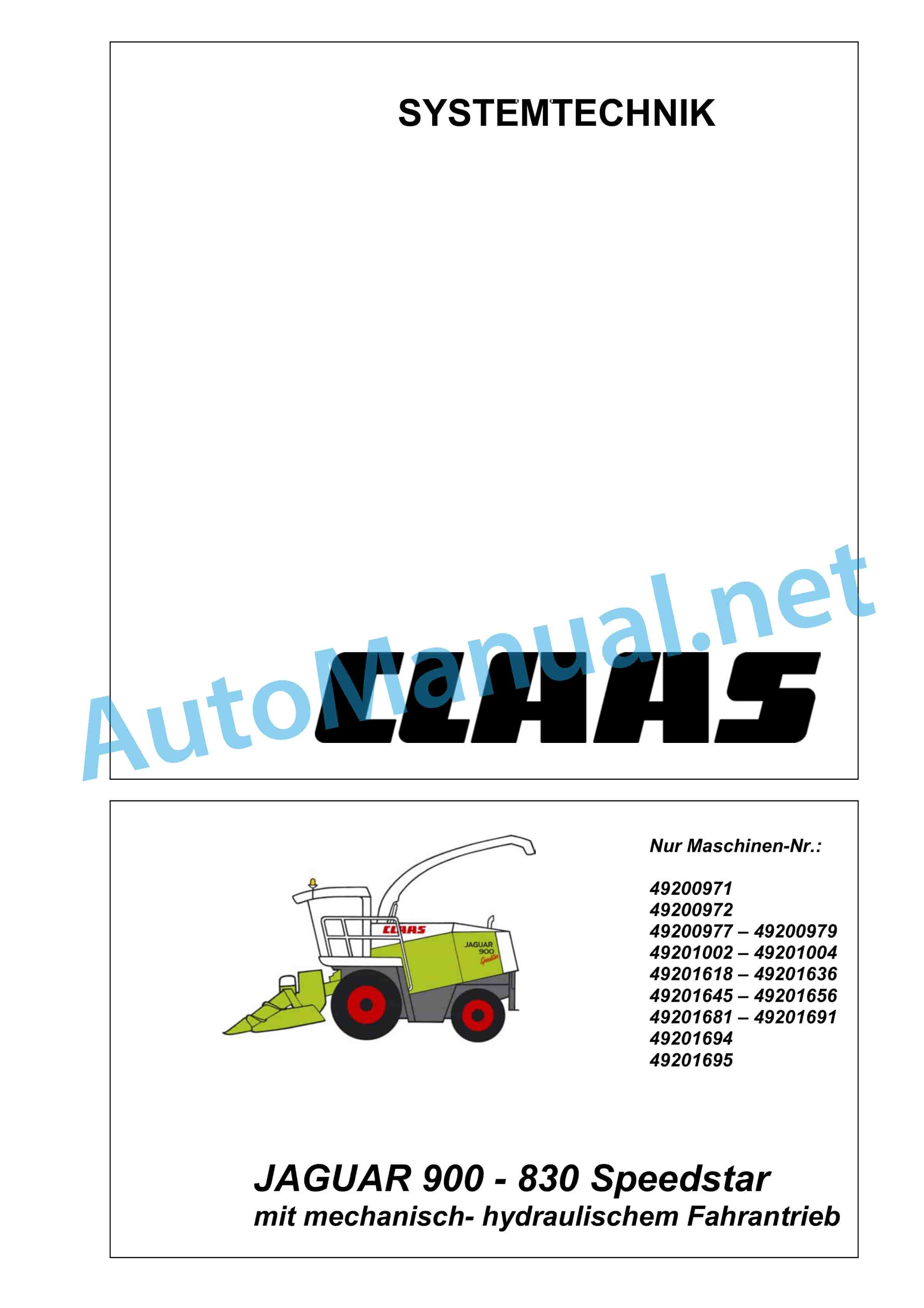
Claas JAGUAR 900-830 (492) Forage Harvesters Technical System DE
$300.00
- Model: JAGUAR 900-830 (492) Forage Harvesters
- Type Of Manual: Technical System
- Language: DE
- Format: PDF(s)
- Size: 19.3 MB
File List:
– 00 0290 038 2.pdf
– 00 0293 511 0.pdf
– 00 0298 673 3.pdf
– 00 0298 674 5.pdf
– 00 0298 845 2.pdf
– 00 0305 862 0.pdf
00 0290 038 2.pdf
Table of Content:
1 JAGUAR 900 – 810
2 Table of Contents
3 CCN Declaration
3.1 CCN (CLAAS Component Number)
4 CCN (CLAAS Component Number)
5 Introduction
5.1 Validity of the instructions
6 75 Central lubrication
6.1 7505 Container, pump
6.2 7515 Lubrication system / lines
7 92 Diagnosis
7.1 Error codes
00 0293 511 0.pdf
Table of Content:
1 System technology Fieldshuttle
2 Hydraulics
2.1 1.0 Total hydraulics
2.2 2.0 Steering hydraulics
2.3 3.0 Working hydraulics
2.4 4.0 Low pressure hydraulics for FIELDSHUTTLE Type: T, CSL, CHL
2.5 5.0 Travel hydraulics
2.6 6.0 Location of the components
3 Electrics
3.1 1.1 Electrics Fieldshuttle CHL container control
3.2 2.1 Electrics Fieldshuttle CSL container control
3.3 3.1 Electrics travel drive Fieldshuttle T, CHL, CSL with mechanical-hydraulic travel drive Up to mach. no.: 492 02560
3.4 3.2 Electrics travel drive Fieldshuttle T, CHL, CSL with mechanical-hydraulic travel drive From mach. no.: 492 02561
3.5 3.3 Electrics travel drive Fieldshuttle T, CHL, CSL with electro-hydraulic travel drive From mach. no.: 492 03342
3.6 4.1 Electrics Fieldshuttle CSL EHL (Electro-Hydraulic Steering)
3.7 5.0 Diagnosis EHL EHL (Electro-Hydraulic Steering)
3.8 34a work lighting I Fieldshuttle
3.9 34b Work lighting II Fieldshuttle
4 293 511.0
00 0298 673 3.pdf
Table of Content:
1 Hydraulic system technology JAGUAR 900 – 830
2 1 Total hydraulics
2.1 1.1 Hydraulic circuit diagrams
2.2 1.2 Valve inserts
3 2 Steering hydraulics
3.1 2.1 Hydraulic circuit diagram
3.2 2.2 Functional diagram of the steering hydraulics
3.3 2.3 Checking the steering
3.4 2.4 Autopilot solenoid valve
3.5 2.5 Testing and measuring
4 3 Working hydraulics
4.1 3.1 Hydraulic circuit diagram
4.2 3.2 Main valve: circulation check valve, raise/lower attachment
4.3 3.3 Valve combination with pressure accumulator bladder
4.4 3.4 Hitch solenoid valve
4.5 3.5 Grinding solenoid valve, additional control unit 1, additional control unit 2
4.6 3.6 Corn Crackers
4.7 3.7 Reverse electromagnetic valve attachment
4.8 3.8 Motor attachment reversing drive (226)
4.9 3.9 Discharge elbow swivel drive motor (206)
4.10 3.10 Valve load changeover attachment (612)
4.11 3.11 Valve changeover pressure storage volume (Direct Disc option)
4.12 3.12 Testing and measuring
5 4 Low pressure hydraulics
5.1 4.1 Hydraulic circuit diagram
5.2 4.2 Location of the components
5.3 4.3 Solenoid valve
5.4 4.4 Pressure relief valve
5.5 4.5 Couplin4.7 Flow control valve suction arm drive
5.8 4.8 Extraction arm drive motor (228)
5.9 4.9 Line collector
5.10 4.10 Valve cylinder knife comb
5.11 4.11 Testing and measuring
6 5 Travel hydraulics
6.1 5.1 JAGUAR 20/25 km/h from machine no. 492 01614
6.2 5.2 JAGUAR 20/25km/h from machine no. 492 00133 to machine no. 492 01613
6.3 5.3 JAGUAR 20/25km/h from machine no. 492 00011 to machine no. 492 00132
6.4 5.4 JAGUAR SPEEDSTAR / PROFISTAR with electro-hydraulic control (EFA)
7 6 Vibration dampening
7.1 6.1 How it works
7.2 6.2 Operation
7.3 6.3 Sensors
7.4 6.4 Function
8 7 Compressed air system
8.1 7.1 Circuit diagram trailer brake system
8.2 7.2 Circuit diagram motor throttle / compressed air clutch
10 0298 673.3
00 0298 674 5.pdf
Table of Content:
1 Electric system technology JAGUAR 900 – 830
2 Structure of electrical circuit diagrams
4 central electrics
4.1 Central electrical system 014 171.2 into mach. no. 492-0132
4.2 Central electrical system 014 183.0 from mach. no. 492-0133 to mach. no. 492-1605
4.3 Central electrics 014 183.1 from mach. no. 492-1606
5 Module assignment
5.1 Module view
5.2 Module A6 automatic climate control
5.3 Module A 7 Cabin fan speed controller
5.4 Module A9 AUTOPILOT (ATP)
5.5 Module A10 – On-Board Informator (CAB)
5.6 Module A11 CONTOUR
5.7 Module A14 feed contro- Ejection/silage agent control (KDS) option
6 Fuses and Relays – Circuit Diagram Assignment
7 Error code list / error diagnosis (CIS)
7.1 Error code list
8 circuit diagrams 01a – 43a
8.1 01a Main voltage supply, diesel engine starter, reversing horn – up to mach. no. 492-1605
8.2 01b Main voltage supply, starter diesel engine, reversing horn – from mach. no. 492-1606
8.3 02a Start diesel engine, diesel engine speed adjustment – not for Profistar, not for Speedstar (with electro-hydraulic
8.4 02b Start diesel engine, diesel engine speed adjustment – for Profistar with diesel engine DC OM 502, for Speedstar (with elektro
8.5 02c Start diesel engine, diesel engine speed adjustment – for Profistar with diesel engine DC OM 457, for Speedstar (with elektro
8.6 03a Diesel engine monitoring
8.7 03b Diesel engine monitoring TIER 3
8.8 04a Road travel circuit, circulation check valve – up to machine number 492 ro- from machine number 492 1606
8.10 05a Terminal, keyboard – up to machine number 492-02209
8.11 06a CAN bus, power supply modules – up to machine number 492 – 1605
8.12 06b CAN bus, power supply modules – from machine number 492 – 1606, not for Profistar, not for Speedstar (with elektro
8.13 06c CAN bus, power supply modules – for Profistar, for Speedstar (with electro-hydraulic travel drive)
8.14 07a Main drive – up to machine number 492 – 1605
8.15 07b Main drive – from machine number 492 – 1606
8.16 07c Main drive from machine number 49203523
8.17 09a Grinding device, without automatic counter-blade adjustment up to machine number 492 – 0132
8.18 09b Grinding device, without automatic counter-blade adjustment from machine number 492 – 0133
8.19 09c Grinding device, with automatic counter-blade adjustment – up to machine number 492 – 0132
8.20 09d Grinding device, with autoentiomete
8.21 09e Grinding device, with automatic counter-blade adjustment – operation via CIS terminal (A30)
8.22 10a Automatic counterblade adjustment, – operation via potentiometer counterblade distance preselection (R9)
8.23 10b Automatic counterblade adjustment, operation via CIS terminal (A30)
8.24 11a Corn Cracker Setting
8.25 12a knife comb
8.26 13a automatic manifold swivel
8.27 13b Automatic manifold swivel system (With option module A73 ejection / silage agent control – adjustable pump in the water tank)
8.28 14a Swivel discharge spout, raise/lower discharge spout
8.29 15a ejection flap near / far
8.30 17a attachment drive, metal detector
8.31 18a stone detector
8.32 19a Reel control drive
8.33 20a raise/lower attachment, – without lateral control
8.34 20b raise/lower attachment, – with lateral control
8.35 21a Additional control unit 1 – fold attachment, raise/lower roller presser, raise/lower reel
8.36 21b Additional control unit 2 – reel horizontal adjustment, additional control unit hitch
8.37 24a CONTOUR / AUTOCONTOUR, vibration dampening
8.38 25a Direct Disc (speed monitoring)
8.39 26a Machine monitoring – up to machine number 492 – 1914
8.40 26b Machine monitoring – from machine number 492 1916, not for Profistar, not for Speedstar (with electro-hydraulic travel drive)
8.41 26c Machine monitoring – for Profistar, for Speedstar (with electro-hydraulic travel drive, up to machine no. 49205322)
8.42 26d Machine monitoring – for Profistar, for Speedstar (with electro-hydraulic travel drive, from machine no. 49205323, with hydraulic oil temperature sensor (B123) )
8.43 27a Quantimeter (FEM)
8.44 28a AUTOPILOT – button system up to machine number 492 – 0132
8.45 28b AUTOPILOT – button system from machine number 492 – 0133
8.46 28c AUTOPILOT laser up to machine number 492 – 0132
8.47 28d AUTOPIlubrication system, servo circuit
8.49 31a flashing system (Europe)
8.50 31b indicator system (USA)
8.51 32a main circuit light, taillight, position light
8.52 33a low beam, high beam, rotating beacon without additional driving light
8.53 33b Low beam, high beam, rotating beacon – with additional driving light
8.54 34a work lighting I
8.55 34b Work lighting II
8.56 35a Horn, brake light
8.57 36a instrument lighting, radio, mirror adjustment
8.58 37a windshield wiper, windshield washer system – for windshield wipers with clockwise rotation
8.59 37b Windshield wiper, windshield washer system – for windshield wipers with clockwise and counterclockwise rotation
8.60 38a compressor cooling system
8.61 38b automatic climate control
8.62 39a Silage additive device – up to machine number 492 -0132
8.63 39b Silage additive device – from machine number 492 -0133
ule A73 ejection / silage agent control (adjustable pump in the water tank)
8.65 40a additional sockets, fuse tester
8.66 42a trailer brake system for Speedstar (with electro-hydraulic drive)
8.67 43a Electro-hydraulic travel drive (EFA)
9 component grid
11 0298 674.5
00 0298 845 2.pdf
Table of Content:
1 cover sheet
2 Chapter 1 Contents
3 Chapter 3 Contents Hydraulics
3.1 Hydraulic circuit diagram
3.2 Components
4 Chapter 4 Gear
5 Chapter 5 Vibration dampening
5.1 How it works
5.2 Operation
5.3 Components
6 Chapter 6 Electrics
6.1 1b Main voltage supply, diesel engine starter, reversing horn
6.2 2b Start diesel engine, diesel engine speed adjustment, speed protection travel drive
6.3 13a automatic manifold pivoting
6.4 14b Swivel discharge spout, raise/lower discharge spout
6.5 20a lifting/lowering attachment vibration dampening
6.6 24a CONTOUR System
6.7 29b all-wheel drive, central lubrication system, servo circuit
6.8 35b Signal horn, brake light, travel drive brake valve
6.9 39a Silage additive device from No. 492-0133
7 298 845.2
00 0305 862 0.pdf
Table of Content:
1 LEXIONJAGUARXERION
2 Table of Contents
3 Introduction
3.1 Notes on the instructions
4 Security
4.1 Recognize warnings
5 01 Motor
5.1 0125 Injection/fuel system
John Deere Repair Technical Manual PDF
John Deere 16, 18, 20 and 24HP Onan Engines Component Technical Manual CTM2 (19APR90)
John Deere Repair Technical Manual PDF
John Deere Repair Technical Manual PDF
John Deere Diesel Engines POWERTECH 2.9 L Component Technical Manual CTM126 Spanish
John Deere Repair Technical Manual PDF
John Deere DF Series 150 and 250 Transmissions (ANALOG) Component Technical Manual CTM147 05JUN98
John Deere Repair Technical Manual PDF
John Deere Diesel Engines PowerTech 4.5L and 6.8L – Motor Base Technical Manual 07MAY08 Portuguese
John Deere Repair Technical Manual PDF
John Deere Repair Technical Manual PDF
John Deere Repair Technical Manual PDF
John Deere Repair Technical Manual PDF
John Deere Repair Technical Manual PDF

