Claas AXION 850-810 (A09) Tractor Operator Manual DE
$50.00
- Model: AXION 850-810 (A09) Tractor
- Type Of Manual: Operator Manual
- Language: DE
- Format: PDF(s)
- Size: 70.5 MB
File List:
– 00 1117 045 1.pdf
– 00 1118 559 0.pdf
– 00 1140 877 0.pdf
– 00 1170 294 2.pdf
– 00 1171 313 0.pdf
00 1117 045 1.pdf
Table of Content:
1 recommendations
2 DESCRIPTION
3 DESCRIPTION: Symbols of the chapters
4 A – MARKING – TYPE APPROVAL – SAFETY
4.1 Identifier
4.2 Type approval
4.3 Security
5 B – Driver’s cab
5.1 Driving and working environment
5.2 Lighting, signaling and safety
5.3 Main ignition switch
5.4 Multifunctional armrest
5.6 Steering wheel
5.7 Dashboard
5.8 Display
5.9 Natural ventilation and windows
5.10 Heater – ventilation fan – manual air conditioning
5.11 Heating/ventilation with automatic air conditioning
5.12 Cab suspension
6 C – ELECTRICAL SYSTEM
6.1 Lighting connection trailer/implement
6.2 Connection for electrical control block
6.3 Event counter connection
6.4 ISO socket
6.5 DEVICE FOR INSTALLING A CONTROL CABIN IN THE CAB
6.6 Battery
6.7 Battery interruption
6.8 Fuses and relays
7 D -Motor
7.1 CHARACTERISTICS
7.3 Security
7.4 Operating the motor
7.5 Claas power management
8 E – Gearbox
8.1 Gear properties
8.3 Security
8.4 Manual transmission
8.5 Rear axle
8.6 Working with the tractor stationary
8.7 Trailer operation
9 F – FRONT AXLE
9.1 Front axle
9.2 Mechanical protection
9.3 Switching on the front axle
9.4 Differential lock
9.5 Proactiv suspension
10 G – Hydraulics – Rear power lift and rear coupling
10.1 Technical data
10.2 Hydraulics
10.3 Power lift
10.4 Towing devices
11 H – FRONT PTO, HITCH AND CLUTCH
11.1 FRONT LIFT
11.2 Front PTO
11.3 FRONT LIFT
11.4 Front PTO
12 I -on-board computer
12.1 “Cebis” Terminal
12.2 Claas Sequence Management
13 J – TIRES AND WHEELS
13.2 Track widths
13.3 SPECIAL CASES
14 K – dimensions, weight, filling quantities and ballasting
14.1 Dimensions and weight
14.2 Filling quantities
14.3 Ballasting
15 L – MAINTENANCE
15.1 GENERAL
15.2 Deadline
15.3 Bleeding the injection circuit
15.4 OVERVIEW OF MAINTENANCE WORK PERFORMED
16 M – Mandatory warranty work
16.1 WORK TO BE PERFORMED UNDER THE CONTRACTUAL WARRANTY
00 1118 559 0.pdf
Table of Content:
1 recommendations
1.1 For your safety
1.2 Proper use
2 Description
3 DESCRIPTION: Symbols of the chapters
4 CHAPITRE_TDM_N3_TDM-02A.pdf
4.1 Identifier A.2
4.2 Type approval A.4
4.3 SAFETY A.5
4.4 Driving and working environment B.2
4.5 Lighting, signaling and safety B.6
4.6 Main ignition switch B.13
4.7 Multifunctional armrest B.14
4.8 Seat B.15
4.9 Steering wheel B.18
4.10 Dashboard B.19
4.11 Display B.26
4.12 Natural ventilation and windows B.27
4.13 Heating – ventilation fan – manual air conditioning B.30
4.14 Heating/ventilation with automatic air conditioning B.32
4.15 Cab suspension B.35
4.16 Lighting connection trailer/implement C.2
4.17 Connection for electrical control block C.3
4.18 Event counter connection C.4
4.19 ISO socket C.5
4.20 Pre-equipment for installing a control unit on the cab C.6
4.21 Battery C.7
4.22 Battery interruption C.8
4.23 Fuses and relays C.9
4.24 Technical data D.2
4.25 Displays D.3
4.26 SAFETY D.4
4.27 Operating the motor D.6
4.28 Claas power management D.15
4.29 Fuel D.16
4.30 Gear properties E.2
4.31 Displays E.25
4.32 SAFETY E.27
4.33 Manual transmission E.31
4.34 Rear axle E.45
4.35 Working with the tractor stationary E.60
4.36 Trailer operation E.61
4.37 Front axle F.2
4.38 Mechanical protection F.4
4.39 Activation of the front axle F.5
4.40 Differential lock F.8
4.41 Proactiv suspension F.11
4.42 Technical data G.2
4.43 Hydraulics G.4
4.44 Power lift G.18
4.45 Towing devices G.29
4.46 Front power lift H.2
4.47 Front PTO H.3
4.48 Front power lift H.4
4.49 Front PTO H.10
4.50 Cebis Terminal I.2
4.51 Claas Sequence Management I.55
4.52 Tire J.2
4.53 Gauges J.6
4.54 SPECIAL CASES J.42
4.55 Dimensions and weight K.2
4.56 Filling quantities K.4
4.57 Ballasting K.6
4.58 General L.2
4.59 Deadline L.3
4.60 Bleeding the injection circuit L.36
4.61 Maintenance and customer service booklet L.37
4.62 WORK TO BE PERFORMED UNDER THE CONTRACTUAL WARRANTY M.2
5 AXION_800_N3_CHAPITRE_A_02A.pdf
5.1 A – MARKING – TYPE APPROVAL – SAFETY
6 AXION_800_N3_CHAPITRE_B_02A.pdf
6.1 B – Driver’s cab
7 AXION_800_N3_CHAPITRE_C_02A.pdf
7.1 C – ELECTRICAL SYSTEM
8 AXION_800_N3_CHAPITRE_D_02A.pdf
8.1 D -MOTOR
9 AXION_800_N3_CHAPITRE_E_02A.pdf
9.1 E – Gearbox
10 AXION_800_N3_CHAPITRE_F_02A.pdf
10.1 F – FRONT AXLE
11 AXION_800_N3_CHAPITRE_G_02A.pdf
11.1 G – Hydraulics – Rear power lift and rear coupling
12 AXION_800_N3_CHAPITRE_H_02A.pdf
12.1 H – FRONT PTO, HITCH AND CLUTCH
13 AXION_800_N3_CHAPITRE_I_02A.pdf
13.1 I -on-board computer
14 AXION_800_N3_CHAPITRE_J_02A.pdf
14.1 J – TIRES AND WHEELS
15 AXION_800_N3_CHAPITRE_K_02A.pdf
15.1 K – Dimensions, weight, filling quantities and ballasting
16 AXION_800_N3_CHAPITRE_L_02A.pdf
16.1 L – MAINTENANCE
17 AXION_800_N3_CHAPITRE_M_02A.pdf
17.1 M – Binding warranty work
18 00 11 185 590_COUV_DOS_DE.pdf
18.1 AXION 810-820-830-840-850 – DE – 11.07
19 00 11 185 590_COUV_DOS_DE.pdf
19.1 AXION 810-820-830-840-850 – DE – 11.07
00 1140 877 0.pdf
Table of Content:
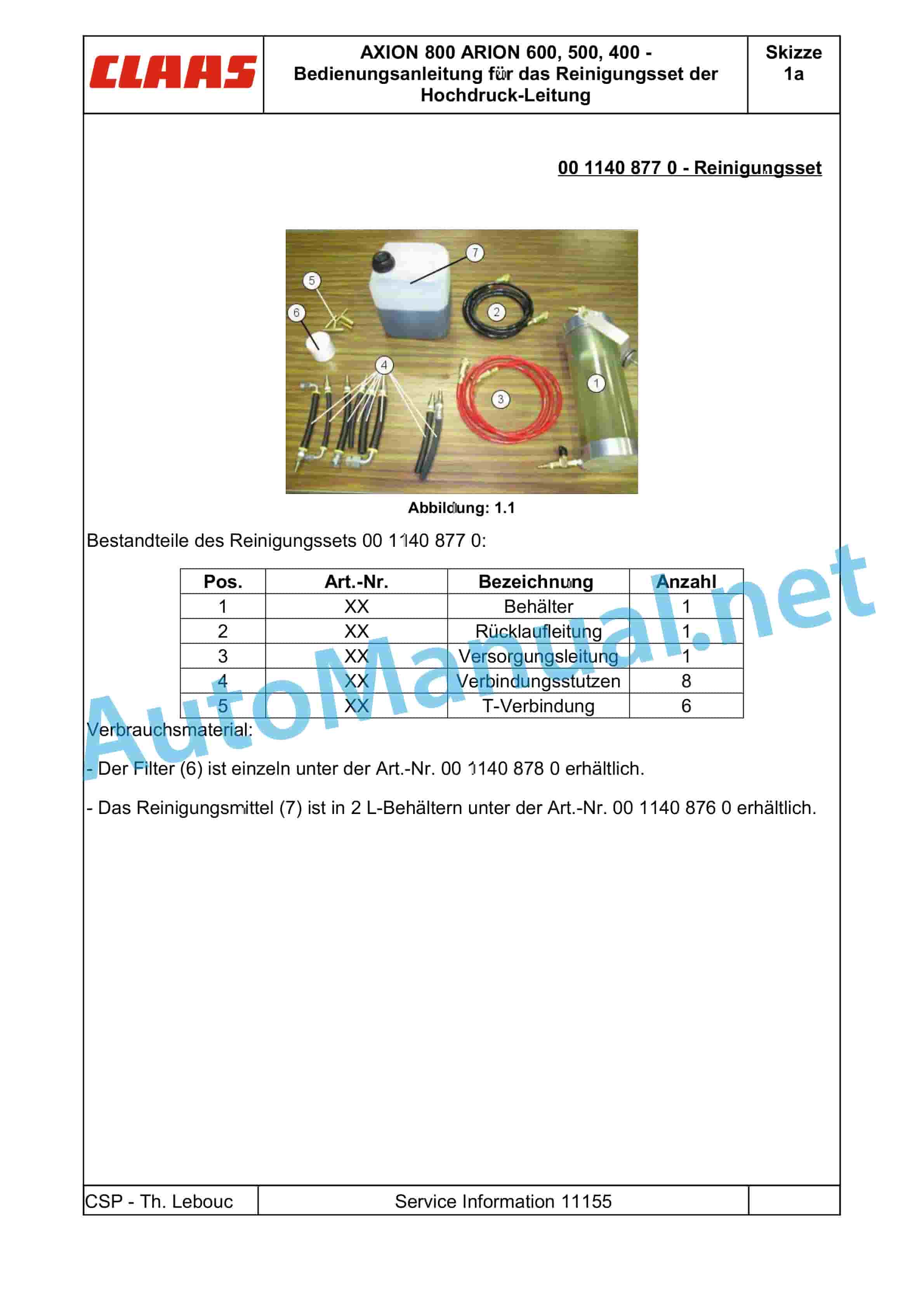
1 AXION 800 ARION 600, 500, 400 – Operating instructions for the high-pressure line cleaning set
00 1170 294 2.pdf
Table of Content:
1 AXION 900-800ARION 600-500-400
2 Table of Contents
3 1 Introduction
3.1 1.1 Notes on the instructions
4 2 Prepare tractor
4.1 2.1 Attachments and machine housing
00 1171 313 0.pdf
Table of Content:
1 AXION 900-800 CEBISARION 600-500 CEBIS
2 Table of Contents
3 1 Introduction
3.1 1.1 Notes on the instructions
4 2 Control and display elements
4.1 2.1 CEBIS
John Deere Repair Technical Manual PDF
John Deere Repair Technical Manual PDF
John Deere PowerTech M 10.5 L and 12.5 L Diesel Engines COMPONENT TECHNICAL MANUAL CTM100 10MAY11
John Deere Repair Technical Manual PDF
John Deere Repair Technical Manual PDF
John Deere Repair Technical Manual PDF
John Deere Repair Technical Manual PDF
John Deere Diesel Engines POWERTECH 2.9 L Component Technical Manual CTM126 Spanish
John Deere Repair Technical Manual PDF
John Deere DF Series 150 and 250 Transmissions (ANALOG) Component Technical Manual CTM147 05JUN98
John Deere Repair Technical Manual PDF
John Deere Transmission Control Unit Component Technical Manual CTM157 15JUL05
John Deere Repair Technical Manual PDF
John Deere Repair Technical Manual PDF

