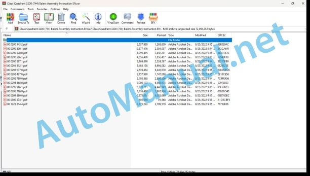
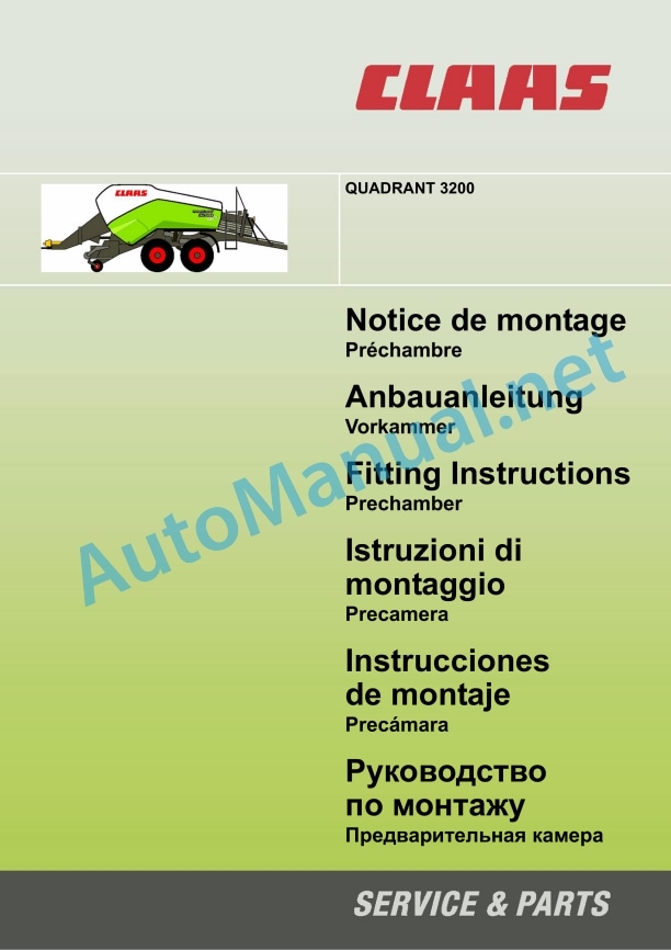
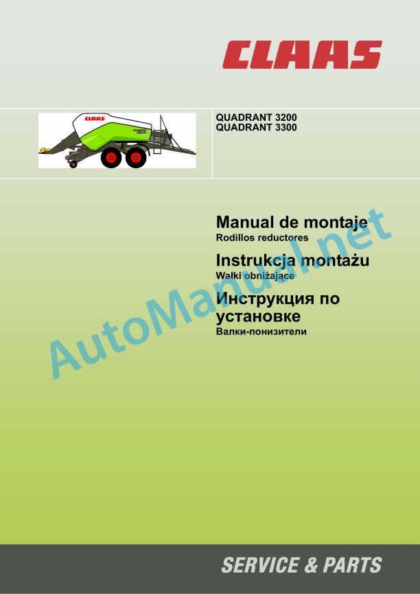
Claas Quadrant 3200 (744) Balers Assembly Instruction EN
$50.00
- Model: Quadrant 3200 (744) Balers
- Type Of Manual: Assembly Instruction
- Language: EN
- Format: PDF(s)
- Size: 50.9 MB
File List:
00 0290 143 2.pdf
00 0290 500 1.pdf
00 0290 520 0.pdf
00 0290 586 1.pdf
00 0290 587 1.pdf
00 0291 312 1.pdf
00 0292 077 0.pdf
00 0292 437 0.pdf
00 0292 780 0.pdf
00 0294 468 0.pdf
00 0295 966 1.pdf
00 0296 786 0.pdf
00 0299 499 0.pdf
00 0300 374 1.pdf
00 1325 214 4.pdf
00 0290 500 1.pdf:
QUADRANT 2200 AdvantageQUADRANT 3200QUADRANT 3400
Table of contents
1 To this manual
1.1 General Information
1.1.1 General points
1.1.2 Machines that can be equipped
2.1 General Information
2.1.1 General points
2.1.2 Use in accordance with the original specifications
2.2 Safety instructions
2.2.1 Definition of hazard information
2.2.2 General safety and accident prevention advice
2.2.3 Parking the machine
3 Bill of material
3.1 Parts kit
3.1.1 Drawbar intermediate plate – 00 0863 234.1
4 Mounting
4.1 Introduction
4.1.1 General points
4.2 Machine preparation
4.2.1 Securing the baler
4.2.2 Removing the coupling
4.3 Fitting the kit
4.3.1 Fitting the intermediate plate
4.3.2 Fitting the coupling
4.4 Checks
4.4.1 Amplitude of travel
4.4.2 Play between the intermediate plate and the complete drawbar
4.4.3 Tightening torques
00 0290 520 0.pdf:
QUADRANT 2200 AdvantageQUADRANT 3200
Table of contents
1 To this manual
1.1 General Information
1.1.1 General points
1.1.2 Machines that can be fitted
2.1 General Information
2.1.1 General points
2.1.2 Use in accordance with the original specifications
2.2 Safety instructions
2.2.1 Definition of hazard information
2.2.2 General safety and accident prevention advice
2.2.3 Parking the machine
3 Bill of material
3.1 Parts kit
3.1.1 Kit 00 0856 345.0 – Balers with welded ladder
3.1.2 Kit 00 0863 952.0 – Balers with aluminium ladder
4 Mounting
4.1 General Information
4.1.1 Tightening torques
4.2 Machine preparation
4.2.1 Securing the baler
4.2.2 Removing the back guard
4.3 Fitting the kit
4.3.1 Assemble and fit the left-hand safety guard
For balers up to 756 00265 and 744 00844, equipped with a welded ladder
QUADRANT 2200 Advantage
QUADRANT 3200
QUADRANT 3200 and 2200 Advantage
4.3.2 Fit the left-hand safety guard
For balers from 756 00266 and 744 00845, equipped with an aluminium ladder
4.3.3 Fit the back support
4.3.4 Assemble and fit the right-hand safety guard
For balers up to 756 00265 and 744 00844, equipped with an aluminium ladder
QUADRANT 2200 Advantage
QUADRANT 3200
4.3.5 Assemble and fit the right-hand safety guard
For balers from 756 00266 and 744 00845, equipped with an aluminium ladder
4.3.6 Fit the front right handle
For balers up to 756 00265 and 744 00844, equipped with a welded ladder
00 0290 586 1.pdf:
QUADRANT 3200
Table of contents
1 To this manual
1.1 General Information
1.1.1 General points
1.1.2 Machines that can be equipped
2.1 General Information
2.1.1 General points
2.1.2 Use in accordance with the original specifications
2.2 Safety instructions
2.2.1 Definition of hazard information
2.2.2 General safety and accident prevention advice
2.2.3 Parking the machine
3 Bill of material
3.1 Parts kit
3.1.1 Kit 00 0863 322.0 – Drawbar stiffener kit
4 Mounting
4.1 Machine preparation
4.1.1 Securing the baler
4.1.2 Removing the automatic lubrication pump
4.1.3 Preparing the weld areas
4.2 Fitting the kit
4.2.1 Welding the stiffeners
4.2.2 Fitting the automatic lubrication pump
00 0290 587 1.pdf:
QUADRANT 2200 AdvantageQUADRANT 3200
Table of contents
1 To this manual
1.1 General Information
1.1.1 General points
1.1.2 Machines that can be equipped
2.1 General Information
2.1.1 General points
2.1.2 Use in accordance with the original specifications
2.2 Safety instructions
2.2.1 Definition of hazard information
2.2.2 General safety and accident prevention advice
2.2.3 Parking the machine
3 Bill of material
3.1 Parts kit
3.1.1 Kit 00 0867 225.0 – Roller locking kit
4 Mounting
4.1 General Information
4.1.1 Tightening torques
4.2 Machine preparation
4.2.1 Securing the baler
4.2.2 Preparing the bale chute
4.3 Fitting the kit
4.3.1 Premounting the roller locking device
4.3.2 Fitting the roller locking discs
4.3.3 Fitting the roller locking device
00 0291 312 1.pdf:
QUADRANT 3200
Table of contents
1 To this manual
1.1 General Information
1.1.1 General points
1.1.2 Machines that can be equipped
2.1 General Information
2.1.1 General points
2.1.2 Use in accordance with the original specifications
2.2 Safety instructions
2.2.1 Definition of hazard information
2.2.2 General safety and accident prevention advice
2.2.3 Parking the machine
3 Bill of material
3.1 Parts kit
3.1.1 Kit 00 1326 030.0 – Stiffener kit QUADRANT 3200
Kit 00 1326 031.0 – Middle frame stiffener kit
Kit 00 1326 032.0 – Rotor frame stiffener kit
4 Mounting
4.1 Machine preparation
4.1.1 Securing the baler
4.1.2 Preparing the machine for the central frame stiffener
Removing the twine boxes
Removing the knotter cover
Removing the front panel
Removing the tying release control
Preparing the weld areas
4.1.3 Preparing the machine for the rotor frame stiffener
Removing the pick-up
Preparing the weld areas
4.2 Fitting the kit
4.2.1 Welding the stiffeners – Central frame
4.2.2 Welding the stiffeners – Rotor frame
4.3 Mounting
4.3.1 Reassembling the machine for the central frame stiffener
Fitting the front panel
Fitting the knotter cover
Fitting the tying release control
Fitting the twine boxes
4.3.2 Reassembling the machine for the rotor frame stiffener
Fitting the pick-up
00 0292 077 0.pdf:
QUADRANT 3200QUADRANT 2200 Advantage
Table of contents
1 To this manual
1.1 General Information
1.1.1 General points
1.1.2 Machines that can be equipped
2.1 General Information
2.1.1 General points
2.1.2 Use in accordance with the original specifications
2.2 Safety instructions
2.2.1 Definition of hazard information
2.2.2 General safety and accident prevention advice
2.2.3 Parking the machine
3 Bill of material
3.1 Parts kit
3.1.1 Kit 00 1326 370.0 – Pick-up modification kit for chopper
4 Mounting
4.1 Machine preparation
4.1.1 Securing the baler
4.1.2 Removing the pick-up
Pick-up lift
Right-hand side
Left-hand side
4.2 Fitting the kit
4.2.1 Preparing the pick-up
Right-hand side
Left-hand side
Middle section
4.3 Mounting
4.3.1 Fitting the pick-up
Right-hand side
Left-hand side
Adjusting the chain tensioner
Removing the lock
Pick-up lift
00 0292 780 0.pdf:
QUADRANT 3200QUADRANT 3300
Table of contents
1 To this manual
1.1 General Information
1.1.1 General points
1.1.2 Machines that can be equipped
2.1 General Information
2.1.1 General points
2.1.2 Use in accordance with the original specifications
2.2 Safety instructions
2.2.1 Definition of hazard information
2.2.2 General safety and accident prevention advice
2.2.3 Parking the machine
3 Bill of material
3.1 Parts kit
3.1.1 Kit 00 1327 719.0 – QUADRANT 3200/3300 motorised flattening rollers
4 Mounting
4.1 Machine preparation
4.1.1 Securing the baler
4.1.2 Machine preparation
Removing the existing flattening rollers
QUADRANT 3300
QUADRANT 3200
4.2 Fitting the kit
4.2.1 Assembling the kit
00 0294 468 0.pdf:
QUADRANT 3200
Table of contents
1 To this manual
1.1 General Information
1.1.1 General points
1.1.2 Machines that can be equipped
2.1 General Information
2.1.1 General points
2.1.2 Use in accordance with the original specifications
2.2 Safety instructions
2.2.1 Definition of hazard information
2.2.2 General safety and accident prevention advice
2.2.3 Parking the machine
3 Bill of material
3.1 Parts kit
3.1.1 Kit 00 1326 046.0 – QUADRANT 3200 Cross member stiffener kit
4 Mounting
4.1 Machine preparation
4.1.1 Securing the baler
4.1.2 Preparing the machine for the cross member stiffener
Removing the bale ramp
Removing the right-hand section
Removing the left-hand section
Removing the metering wheel
Removing the lower flap
Left-hand side
Right-hand side
Removing the bale ejector
Removing the hydraulic ducts
Protecting the working area
Cutting the cross member
Left-hand side
Right-hand side
4.2 Fitting the kit
4.2.1 Welding the cross member kit
Positioning the stiffeners
Left-hand stiffener
Right-hand stiffener
Welding the stiffeners
Left-hand stiffener
Right-hand stiffener
Positioning the cross member
Welding the cross member
Positioning the gussets
Welding the gussets
4.3 Mounting
4.3.1 Reassembling the machine with the cross member stiffener
Fitting the hydraulic ducts
Fitting the bale ejector
Fitting the lower flap
Left-hand side
Right-hand side
Fitting the metering wheel
Fitting the right-hand section
Fitting the left-hand section
Fitting the bale ramp
00 0295 966 ������1.pdf:
1 Introduction
1.1 Generalities
1.2 Machines to equip
2 Safety instructions
2.1 Important
2.1.1 Generalities
2.1.2 Use according to destination
2.2 Safety instructions
2.2.1 Characterization of indications on the dangers
2.2.2 General safety and acci prevention instructions
2.2.3 Parking the machine
3 Lot of pieces
3.1 QUADRANT 3200 – 00 0863 802 0e anteroom
4.1 Advice and safety of the machine
4.2 Tightening torques
4.3 Assembly of the pre-Preparation of the anteroom
4.3.2 Removal of the old bedroom
4.3.3 Installation of the nouvelle pr��chambre
4.4 Mise �� jour du program
4.4.1 Branching of the CDS
4.4.2 Mise �� jour du program
4.5 Manual greasing of the press
4.5.1 C��t�� droit – all 50 h
4.5.2 C��t�� gauche – all 50 h
5 Connection diagrams
5.1 Modification of chapter 09a of the Technique du syst��me ��lectrique notice
5.1.1 Connection diagram (DIN A3)
5.1.2 Designations
5.1.3 Table of measured values
6 CLAAS COMMUNICATOR
6.1 CLAAS COMMUNICATOR settings
6.1.1 Force of retention
7 List of spare parts
7.1 Extract 1
1 Introduction
1.1 General
1.2 Auszurustende Maschinen
2 Sicherheitsvorschriften
2.1 Important
2.1.1 General
2.1.2 Benutzung gebestimmung
2.2 Sicherheitsvorschriften
2.2.1 Kennzeichnung der Gefahrenhinweise
2nd Accidentverh��tung
2.2.3 Parking the machine
3 pVorkammer
4.1 Hinweise und Sicherung der Maschine
4.2 Tightening torque
4.3 Montage der Vorkammer
4.3.1 Vorkammer preparation
4.3.2 Ausbau der alten Vorkammer
4.3.3 Einbau der neuen Vorkammer
4.4 Updating the Programs
4.4.1 Anschlie��en des CDS
4.4.2 Update of Programs
4.5 Manuale Schmierung der Presse
4.5.1 Rechte Seite – alle 50 h
4.5.2 Left Side – alle 50 h
5 Schaltpl��ne
5.1 ��nderung des Kapitel 09a der Anleitung Technik des elektrischen Systems
5.1.1 Circuit diagram (DIN A3)
5.1.2 Bezeichnungen
5.1.3 Messwerttabelle
6 CLAAS COMMUNICATOR
6.1 Settings from CLAAS COMMUNICATOR
6.1.1 R��ckhaltekraft
7 Ersatzteilliste
7.1 Withdrawal 1
1 Introduction
1.1 General points
1.2 Machines that can be fi2 Safety advice
2.1 Important
2.1.1 General points
2.1.2 Use in accordance with original specifications
2.2 S2.1 Definition of hazard information
2.2.2 General safety and accident prevention advice
ine
3 parts kit
3.1 QUADRANT 3200 – 00 0863 802 0
4 Precompression chamber assembly
4.1 Advice and making the machine safe
4.2 Tightening torques
4.3 Precompression chamber assembly
4.3.1 Preparing the precompression chamber
4.3.2 Remove the old precompression chamber
4.3.3 Fitting the new precompression chamber
4.4 Updating the program
4.4.1 Connecting the CDS
4.4.2 Updating the program
4.5 Manual lubrication of the baler
4.5.1 Right-hand side – every 50 hours
4.5.2 Left-hand side – every 50 hours
5 Circuit diagrams
5.1 Modification in section 09a of the Electrical system technical information manual
5.1.1 Circuit diagram (DIN A3)
5.1.2 Key to diagram
5.1.3 Measuring value table
6 CLAAS COMMUNICATOR
6.1 CLAAS COMMUNICATOR Settings
6.1.1 Retention force
7 Spare parts list
7.1 Extract 1
1 Introduction
1.1 Generality
1.2 Equipment machine
2 Safety instructions
2.1 Important
2.1.1 Generality
2.1.2 Use as intended
2.2 Safety instructions
2.2.1 Characterization of the indications relative to danger
2.2.2 General safety and incident prevention instructions
2.2.3 Parking the machine
3 Lotto di pezzi
3.1 QUADRANT 3200 – 00 0863 802 0
4 Assembly of the precamera
4.1 Advice and safety of the machine
4.2 Coppie di serraggio
4.3 Assembly of the pre-camera
4.3.1 Preparation of the precamera
4.3.2 Disassembly of the old pre-camera
4.3.3 Mounting the new pre-camera
4.4 Program update
4.4.1 Connection of the CDS
4.4.2 Program update
4.5 Manual lubrication of the press
4.5.1 Right side – every 50 h
4.5.2 Left side – every 50 h
5 Electrical diagram
5.1 Modification of chapter 09a of the manual Electrical system technology
5.1.1 Electrical diagram (DIN A3)
5.1.2 Designations
5.1.3 Table of measurements
6 CLAAS COMMUNICATOR
6.1 CLAAS COMMUNICATOR settings
6.1.1 Prechamber pressure
7 List of spare parts
7.1 Stratum 1
1 Introduction
1.1 General information
1.2 Applicable machines
2 Safety rules
2.1 Important
2.1.1 General information
2.1.2 Use according to the application
2.2 Security rules
2.2.1 Symbols applicable to danger indications
2.2.2 General safety and accident prevention rules
2.2.3 Fixing the machine
3 Lot of pieces
3.1 QUADRANT 3200 – 00 0863 802 0
4 Assembling the pre-chamber
4.1 Advice and placement of the machine in a safe position
4.2 Tightening torques
4.3 Assembling the pre-chamber
4.3.1 Preparation of the anteroom
4.3.2 Disassemble the old pre-chamber
4.3.3 Assembly of the new prechamber
4.4 Update of the program
4.4.1 Connection of the CDS
4.4.2 Program update
4.5 Manual greasing of the baler
4.5.1 Right side, every 50 hours
4.5.2 Left side, every 50 hours
5 Connection diagrams
5.1 Modification of chapter 09a of the Electrical system technique document
5.1.1 Connection diagram (DIN A3)
5.1.2 Denominations
5.1.3 Table of measured values
6 CLAAS COMMUNICATOR
6.1 Adjustments of the CLAAS COMMUNICATOR
6.1.1 Retention force
7 List of spare parts
7.1 Extract 1
1 ����������������
1.1 ���������� ����������������
1.2 ���������������������� ������������
2 ���������������� ���� ���������� ������������������������
2.1.1 ���������� ������������O????????? 1
00 0296 786 0.pdf:
QUADRANT 3200
QUADRANT 3300
!>45@60=85
1 Acerca de este manual
2.2.3 Fijaci?n de la m?quina
3 Nomenclature
3.1 Lote de piezas
3.1.1 Kit 00 1327 719.0 Rodillos reductores motorizados QUADRANT 3200/3300
4.1 Preparaci?n de la m?quina
4.1.1 Protecci?n de la empacadora
4.1.2 Preparaci?n de la m?quina
Desmontar los rodillos reductores existentes
4.2 Colocaci?n del kit
4.2.1 Ensamblaje del kit
1 Information about this manual
1.1 General information
1.1.1 General information
1.1.2 Machines adapted to assembly the set
2 Security
2.1 General information
2.1.1 General information
2.1.2 Use as intended
2.2 Safety recommendations
2.2.1 Characteristics of hazard markings
2.2.2 General safety and accident prevention recommendations
2.2.3 Parking the machine
3 List of items
3.1 Parts kit
3.1.1 Set 00 1327 719.0 – Lowering rollers with drive QUADRANT 3200/3300
4.1 Preparing the machine
4.1.1 Securing the press
4.1.2 Preparing the machine
Removal of the existing lowerers
4.2 Kit assembly
4.2.1 Kit assembly
1 Otnositelno ethoy instructions
1.1 Objections
1.1.1 ���������� ����������������
1.1.2 Barrier machines
2 Non-passivity
2.1 Objections
2.1.1 ���������� ����������������
2.1.2 Polishing after marking
2.2 ���������������� ���� ���������� ������������������������
2.2.1 �����������ïS the original specifications
2.2 Safety instructions
2.2.1 Definition of hazard information
2.2.2 General safety and accident prevention advice
2.2.3 Parking the machine
3 Bill of material
3.1 Parts kit
3.1.1 Contents of the kit 00 1351 126 0
4 Mounting
4.1 Introduction
4.1.1 Securing the baler
4.2 Fitting the kit
4.2.1 Fitting the kit
John Deere Repair Technical Manual PDF
John Deere Parts Catalog PDF
John Deere Tractors 7500 Parts Catalog CPCQ26568 30 Jan 02 Portuguese
John Deere Repair Technical Manual PDF
John Deere Repair Technical Manual PDF
John Deere Repair Technical Manual PDF
John Deere Repair Technical Manual PDF
John Deere Repair Technical Manual PDF
John Deere 16, 18, 20 and 24HP Onan Engines Component Technical Manual CTM2 (19APR90)
John Deere Repair Technical Manual PDF
John Deere Repair Technical Manual PDF
John Deere Diesel Engines PowerTech 4.5L and 6.8L – Motor Base Technical Manual 07MAY08 Portuguese

