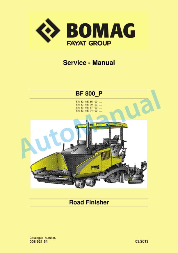
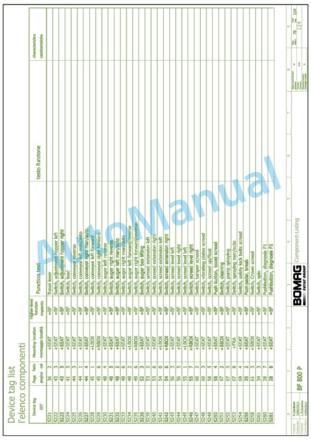
Bomag BF 800 P Road Finisher Service Manual 00892154
$30.00
- Type Of Manual: Service Manual
- Manual ID: 00892154
- Format: PDF
- Size: 59.3MB
- Number of Pages: 1110
- Serial Number:
821837651001, 821837701001, 821837671001, 821837741001
Category: Bomag Service Manual PDF
-
Model List:
- BF 800 P Road Finisher
- 1. BF 800_P
- 1.1. BF 800_P
- 2. General
- 2.1. General
- 2.2. Introduction
- 2.3. General
- 2.4. General
- 2.5. Transport work with cranes and lifting tackle
- 2.6. Precautions and codes of conduct for welding work
- 2.7. Operation of highvoltage systems
- 2.8. Old oils
- 2.9. Hydraulics
- 2.10. Hot fuels
- 2.11. Synthetic rubber
- 2.12. Poisonous substances
- 2.13. Battery
- 2.14. Special safety regulations
- 2.15. The values specified in the table apply for screws
- 2.16. The values specified in the table apply for screws
- 2.17. The values specified in the table apply for screws
- 2.18. The values specified in the table apply for screws
- 2.19. The values specified in the table apply for screws
- 2.20. The values specified in the table apply for screws
- 2.21. The values specified in the table apply for screws
- 2.22. The values specified in the table apply for screws
- 2.23. The values specified in the table apply for screws
- 2.24. The values specified in the table apply for screws
- 2.25. The values specified in the table apply for screws
- 2.26. The values specified in the table apply for screws
- 2.27. The values specified in the table apply for screws
- 2.28. The values specified in the table apply for screws
- 3. Technical data
- 3.1. Technical data
- 3.2.
- 3.3.
- 3.4.
- 4. Maintenance
- 4.1. Maintenance
- 4.2. General notes on maintenance
- 4.3. Fuels and lubricants
- 4.4. Coolant
- 4.5. Mineral oil based hydraulic oil
- 4.6. Gear oil
- 4.7. Lubrication grease
- 5. Engine
- 5.1. Engine
- 5.2. Checking the engine oil level
- 5.3. Checking the engine oil level
- 5.4. Changing engine oil and oil filter cartridge
- 5.5. Replacing the fuel prefilter cartridge, bleed the fuel system
- 5.6. Replace the fuel filter
- 5.7. Check, clean the water separator
- 5.8. Check the coolant level
- 5.9. Change the coolant
- 5.10. Air filter maintenance
- 5.11. Air filter maintenance
- 5.12. Clean the cooling fins on engine and hydraulic oil cooler
- 5.13. Intercooler, drain off oil and condensation water
- 5.14. Adjust the valve clearance
- 5.15. Checking, tensioning, replacing the Vbelt
- 5.16. Replace the crank case ventilation valve
- 5.17. Engine conservation
- 6. Engine electrics
- 6.1. Engine electrics
- 7. Electrics
- 7.1. Electrics
- 7.2. Service the battery, check the main battery switch
- 7.3. Starting the engine with jump leads
- 7.4.
- 7.5. Component overview Electrics
- 7.6. View of control panel
- 7.7. View of control panel
- 7.8. View of control panel
- 8. Error codes general information
- 8.1. Error codes general information
- 9. Input codes
- 9.1. Input codes
- 10. Replacement of components
- 10.1. Replacement of components
- 11. Material hopper, description
- 11.1. Material hopper, description
- 12. Vibrating screed, description
- 12.1. Vibrating screed, description
- 13. Basic settings on the screed
- 13.1. Basic settings on the screed
- 13.2. Bringing the straight crossfalls to zero position
- 13.3. Bringing the straight crossfalls to zero position
- 13.4. Aligning basic screed and mobile sections
- 14. Assembling the screed extensions
- 14.1. Assembling the screed extensions
- 14.2. Assembling the screed extensions
- 14.3. Assembling the screed extensions
- 15. Electric screed heating, repair
- 15.1. Electric screed heating, repair
- 15.2. Faults in the electric heating
- 15.3. Faults in the electric heating
- 15.4. Faults in the electric heating
- 16. Hydraulics
- 16.1. Hydraulics
- 16.2. Component overview hydraulics
- 16.3. Component overview hydraulics
- 16.4. Variable displacement pumps, A4VG28EP to A4VG180EP
- 16.5. Variable displacement pumps, A4VG28EP to A4VG180EP
- 16.6. Travel pump viewed on the machine
- 16.7. Travel pump viewed on the machine
- 16.8. Variable displacement pumps, A10VG28/45/56 EP
- 16.9. Side plates viewed on the machine
- 16.10. Side plates viewed on the machine
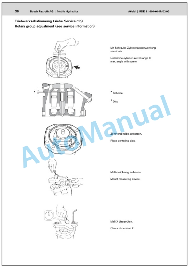
- 16.11. Axial piston pumps, A10VO/VSO 18 to 100 DFR1
- 16.12. Axial piston pumps, A10VO/VSO 18 to 100 DFR1
- 16.13. Pump for fan drive viewed on the machine
- 16.14. Pump for fan drive viewed on the machine
- 16.15. External gear pumps
- 16.16. External gear pumps
- 16.17. Multiple gear pumps
- 16.18. Check the hydraulic oil level
- 16.19. Change hydraulic oil and hydraulic oil filter
- 17. Hydraulics travel circuit
- 17.1. Hydraulics travel circuit
- 17.2. Travel circuit
- 17.3. Travel circuit
- 18. Hydraulics material transport
- 18.1. Hydraulics material transport
- 18.2. Scraper belts
- 18.3. Scraper belts
- 18.4. Conveyor augers
- 18.5. Conveyor augers
- 18.6. Tamping
- 18.7. Tamping
- 18.8. Vibrate
- 18.9. Vibrate
- 19. Hydraulics Service
- 19.1. Hydraulics Service
- 19.2. Fan circuit
- 19.3. Fan circuit
- 19.4. Service (a)
- 19.5. Service (a)
- 19.6. Service (b)
- 19.7. Service (b)
- 20. Tests and adjustments
- 20.1. Tests and adjustments
- 20.2. Checking and adjusting the vibration
- 20.3. Checking and adjusting the vibration
- 20.4. Checking/adjusting tamping
- 20.5. Checking/adjusting the scraper belts
- 20.6. Checking/adjusting the augers
- 20.7. Checking adjusting the service pump/cylinder functions
- 20.8. Checking adjusting the time for screed levelling
- 20.9. Checking/adjusting the hopper wings
- 20.10. Checking/adjusting the mobile screed
- 21. Suppliers documentation
- 21.1. Suppliers documentation
- 21.2.
- 21.3.
- 21.4.
- 21.5.
- 21.6.
- 21.7.
- 21.8.
- 21.9.
- 21.10.
- 21.11.
- 21.12.
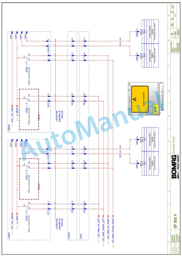
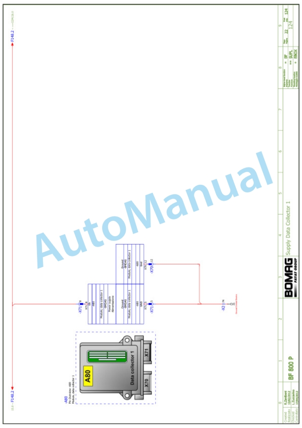
- 22. Circuit diagrams
- 22.1. Circuit diagrams
- 23.
- 23.1.
Rate this product
You may also like
Bomag Service Manual PDF
Bomag BC 472 RB Refuse Compactor Electric, Hydraulic Schematics Diagram 101930001002 – 101930001058
$30.00
Bomag Service Manual PDF
Bomag BC 473 EB-4 Refuse Compactor Electric Schematics Diagram 101930111001 – 101930119999
$30.00
Bomag Service Manual PDF
$30.00
Bomag Service Manual PDF
$30.00
Bomag Service Manual PDF
$30.00
Bomag Service Manual PDF
$30.00
Bomag Service Manual PDF
Bomag BC 571 RB Refuse Compactor Electric, Hydraulic Schematics Diagram 101570621033 – 101570621062
$30.00
Bomag Service Manual PDF
$30.00
Bomag Service Manual PDF
$30.00
Bomag Service Manual PDF
$30.00

