


Bomag Service Manual PDF

Bomag Service Manual PDF
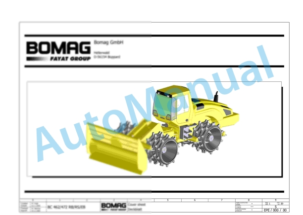
Bomag BC 462 RB Refuse Compactor Electric, Hydraulic Schematics Diagram 101930031001 – 101930031042
Bomag Service Manual PDF
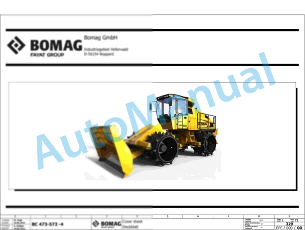
Bomag BC 473 EB-4 Refuse Compactor Electric Schematics Diagram 101930111001 – 101930119999
Bomag Service Manual PDF
Bomag BC 472 RB Refuse Compactor Electric, Hydraulic Schematics Diagram 101930041001 – 101930041022
Bomag Service Manual PDF
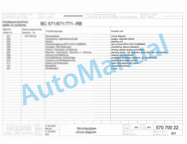
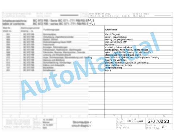
Bomag BC 571 RB Refuse Compactor Electric, Hydraulic Schematics Diagram 101570621033 – 101570621062
Bomag Service Manual PDF
Bomag Service Manual PDF
Bomag Service Manual PDF
Bomag BC 572 RB Refuse Compactor Electric, Hydraulic Schematics Diagram 101570631001 – 101570631163
Bomag Service Manual PDF
Bomag Service Manual PDF