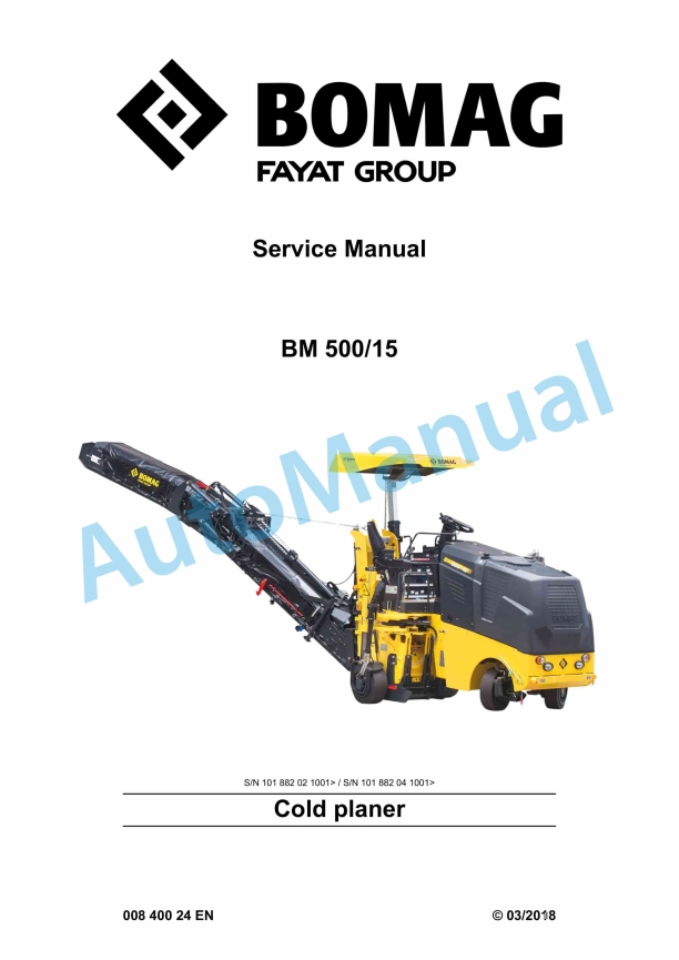
Bomag BM 500-15 Cold Planer Service Manual 00840024
$30.00
- Type Of Manual: Service Manual
- Manual ID: 00840024
- Format: PDF
- Size: 60.9MB
- Number of Pages: 882
- Serial Number:
101882021001 and up
101882041001 and up
Category: Bomag Service Manual PDF
-
Model List:
- BM 500-15 Cold Planer
- 1. Table of contents
- 2. General
- 2.1. Introduction
- 2.2. Concerning your safety
- 2.2.1. Basic prerequisites
- 2.2.2. Definition of responsible persons
- 2.2.3. Basic safety regulations for safe operation
- 2.2.4. Handling fuels and lubricants
- 2.2.5. Loading/transporting the machine
- 2.2.6. Start up procedure
- 2.2.7. Driving the machine, working operation
- 2.2.8. Refuelling
- 2.2.9. Regeneration of exhaust gas aftertreatment system
- 2.2.10. Emergency procedures
- 2.2.11. Maintenance work
- 2.2.12. Repair
- 2.2.13. Signage
- 2.3. Maintenance and repair
- 2.3.1. Preliminary remarks and safety notes
- 2.3.2. Notes on repair
- 2.3.3. Parking the machine in secured condition
- 3. Technical data
- 3.1. Fuels and lubricants
- 3.1.1. Engine oil
- 3.1.2. Fuel
- 3.1.3. Coolant
- 3.1.4. Hydraulic oil
- 3.1.5. Gear oil ISO VG 220
- 3.1.6. Lubrication grease
- 3.1.7. Hightemperature lubrication grease
- 3.2. List of fuels and lubricants
- 3.3. Terms and basis of calculation
- 4. Overview of machine
- 4.1. Component overview Electrics
- 4.2. Component overview hydraulics
- 4.3. Component overview machine assemblies
- 4.3.1. Engine
- 4.3.2. Drive unit
- 4.3.3. Height adjustment and steering
- 4.3.4. Milling unit
- 4.3.5. Milling drum
- 4.3.6. Conveyor system
- 4.3.7. Water system
- 4.4. Overview of maintenance flaps and doors
- 5. Electric systems
- 5.1. Basic principles
- 5.1.1. Deutsch plug, series DT and DTM
- 5.1.2. Clipon technology
- 5.1.3. Magnetic coil plug
- 5.1.4. Telemecanique switch
- 5.2. Operating consoles
- 5.3. Central electrics
- 5.4. Wiring
- 5.5. Description of electrical components
- 5.5.1. Pressure sensor for water spraying system
- 5.5.2. Crossslope sensor
- 5.5.3. Hydraulic oil temperature sensor
- 5.5.4. Side plate wire rope sensor
- 5.6. Fuse assignment
- 5.6.1. Notes on safety
- 5.6.2. Central electrics
- 5.6.3. Main fuses
- 5.7. Input codes
- 5.7.1. Display, layout and operation
- 5.7.2. Resetting to factory settings
- 5.7.3. Calibration of surge currents for height adjustment
- 5.7.4. Switching the unit system over
- 5.7.5. Water tank functions
- 5.7.6. Activation of relay in automatic mode
- 5.7.7. Conveyor belt ON via double and single buttons
- 5.7.8. Driving against the closed brake
- 5.7.9. Speed droop monitoring/display
- 5.7.10. Viscous fan
- 5.7.11. Software version
- 5.7.12. Milling clutch switching processes
- 5.7.13. Reversing with the milling drum switched ON
- 5.7.14. Showing the hydraulic oil temperature
- 5.7.15. 3way milling stage selector switch
- 5.7.16. Showing logged faults
- 5.7.17. Showing saved faults with operating hours
- 5.7.18. Deleting the error log
- 5.8. Replacement of components
- 5.9. Block diagrams
- 5.10. Inspection and maintenance work
- 5.10.1. Maintenance Table
- 5.10.2. Every 500 operating hours
- 5.10.3. As required
- 6. Hydraulic system
- 6.1. Basic principles
- 6.1.1. Open and closed hydraulic circuit
- 6.1.2. Swash plate principle, motor
- 6.1.3. Swash plate principle, pump
- 6.2. Hydraulic components position
- 6.3. Position of hydraulic pumps
- 6.4. Description of hydraulic components
- 6.4.1. Gear pump AZPF
- 6.4.2. Travel pump, A10VG1863 EP
- 6.4.3. Steering valve
- 6.4.4. Description of function
- 6.5. Repairs
- 6.5.1. Changing gear pumps on auxiliary drive of diesel engine
- 6.6. Tests and adjustments
- 6.6.1. Checking and adjusting the levelling
- 6.6.2. Checking and adjusting the roof adjustment
- 6.6.3. Checking and adjusting the clutch operating pressure
- 6.6.4. Checking and adjusting the brake releasing pressure
- 6.6.5. Checking and adjusting the steering pressure
- 6.6.6. Working hydraulics checking and adjusting the MP pressure
- 6.6.7. Checking and adjusting the scraper pressure
- 6.6.8. Checking and adjusting the conveyor belt pressure
- 6.6.9. Checking and adjusting the hydraulic breaker pressure
- 6.6.10. Checking and adjusting the maximum pressure of the travel pump
- 6.7. Inspection and maintenance work
- 6.7.1. Maintenance Table
- 6.7.2. Checks prior to start up
- 6.7.3. Every 250 operating hours
- 6.7.4. Every 500 operating hours
- 6.7.5. Every 1000 operating hours
- 6.7.6. Every 2000 operating hours
- 7. Machine assemblies
- 7.1. Engine
- 7.1.1. Diesel engine
- 7.2. Drive unit
- 7.2.1. Description
- 7.2.2. Repair
- 7.2.3. Inspection and maintenance work
- 7.3. Milling unit
- 7.3.1. Description
- 7.3.2. Repair
- 7.3.3. Inspection and maintenance work
- 7.4. Milling drum
- 7.4.1. Description
- 7.4.2. Repair
- 7.4.3. Inspection and maintenance work
- 7.5. Conveyor system
- 7.5.1. Description
- 7.5.2. Inspection and maintenance work
- 7.6. Water system
- 7.6.1. Description
- 7.6.2. Inspection and maintenance work
- 8. Troubleshooting
- 8.1. Preliminary remarks
- 8.2. Emergency procedures
- 8.2.1. Actuating the emergency stop switch
- 8.2.2. Disconnecting the battery
- 8.2.3. Towing the machine
- 8.3. Functional conditions
- 8.3.1. Functional conditions introduction
- 8.3.2. Functional conditions left side plate
- 8.3.3. Functional conditions right side plate
- 8.3.4. Functional conditions holddown
- 8.3.5. Functional conditions scraper
- 8.3.6. Functional conditions support wheel, rear left
- 8.3.7. Functional conditions support wheel, rear right
- 8.3.8. Functional conditions conveyor belt
- 8.3.9. Functional conditions milling
- 8.3.10. Functional conditions brake
- 8.4. Troubleshooting, electrical systems
- 8.4.1. Measuring method
- 8.4.2. Diagnostics concept
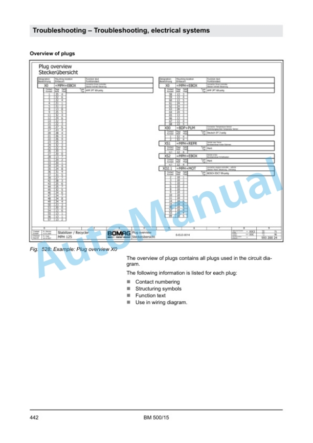
- 8.4.3. Understanding electric circuit diagrams
- 8.4.4. ESX, checking the electric power supply
- 8.4.5. Codes General Information
- 8.4.6. Error codes
- 8.4.7. BOMAG DTC fault code list
- 8.4.8. Query codes
- 8.5. Trouble shooting, hydraulics
- 8.5.1. Troubleshooting table for hydraulic components
- 8.5.2. Troubleshooting axial piston motors
- 8.5.3. Troubleshooting axial piston pumps
- 8.5.4. Insufficient hydraulic power
- 8.6. Trouble shooting, diesel engine
- 8.6.1. Starting the engine with jump leads
- 8.6.2. Bleed the fuel system
- 8.6.3. Engine malfunctions
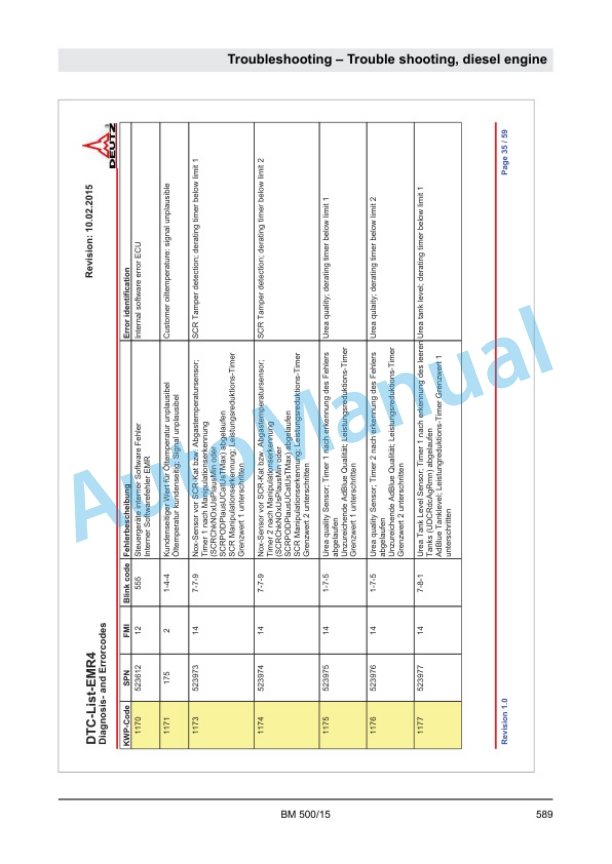
- 8.6.4. Deutz DTC fault code list, EMR4
- 9. Special tools
- 9.1. Available special tools
- 9.1.1. Special tools, electrics
- 9.1.2. Special tools, hydraulic system
- 9.2. List of special tools
- 10. Index
- 11. Appendix
- 11.1. Appendices
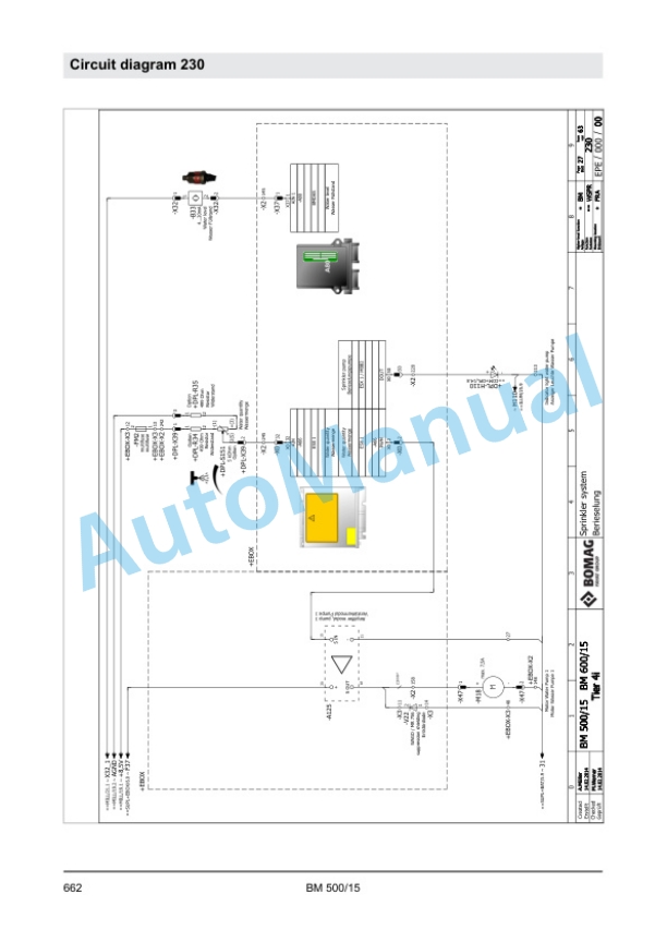
- 11.2. A Circuit diagram 230
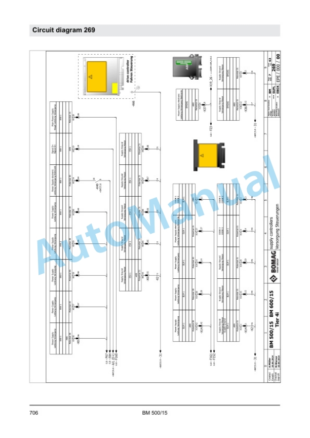
- 11.3. B Circuit diagram 269
- 11.4. C Wiring diagram 296
- 11.5. D Hydraulic diagram 264
- 11.6. E Hydraulic diagram 277
- 11.7. F Hydraulic diagram 343
Rate this product
You may also like
Bomag Service Manual PDF
$30.00
Bomag Service Manual PDF
$30.00
Bomag Service Manual PDF
Bomag BC 472 RB Refuse Compactor Electric, Hydraulic Schematics Diagram 101930041001 – 101930041022
$30.00
Bomag Service Manual PDF
$30.00
Bomag Service Manual PDF
$30.00
Bomag Service Manual PDF
$30.00
Bomag Service Manual PDF
$30.00
Bomag Service Manual PDF
$30.00
Bomag Service Manual PDF
$30.00
Bomag Service Manual PDF
$30.00

