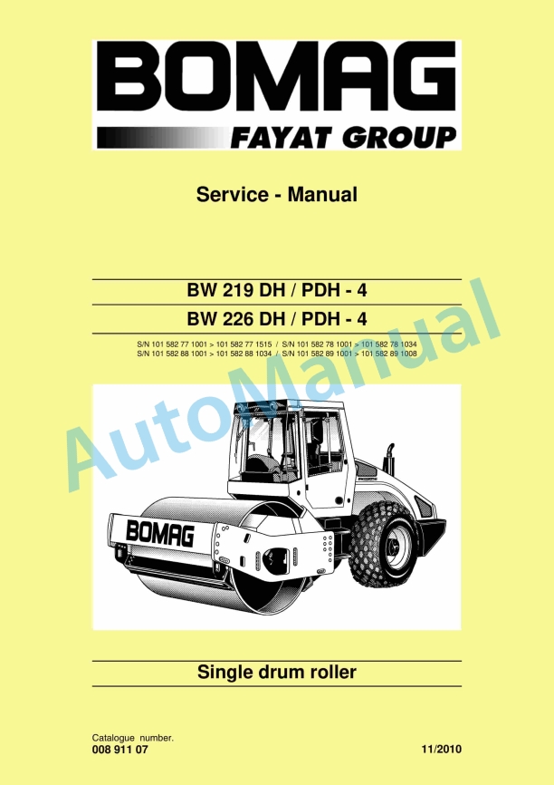
Bomag BW 219 DH-4, BW 219 PDH-4, BW 226 DH-4, BW 226 PDH-4 Single Drum Roller Service Manual 00891107
$30.00
- Type Of Manual: Service Manual
- Manual ID: 00891107
- Format: PDF
- Size: 57.8MB
- Number of Pages: 1440
- Serial Number:
101582771001 – 101582771515
101582781001 – 101582781034
101582881001 – 101582881034
101582891001 – 101582891008
-
Model List:
- BW 219 DH-4 Single Drum Roller
- BW 219 PDH-4 Single Drum Roller
- BW 226 DH-4 Single Drum Roller
- BW 226 PDH-4 Single Drum Roller
- 1. BW 219 DH / PDH 4
- 1.1. BW 219 DH / PDH 4
- 2.
- 2.1.
- 3. General
- 3.1. General
- 3.2. Introduction
- 3.3. General
- 3.4. General
- 3.5. Transport work with cranes and lifting tackle
- 3.6. Precautions and codes of conduct for welding work
- 3.7. Old oils
- 3.8. Hydraulics
- 3.9. Hot fuels
- 3.10. Synthetic rubber
- 3.11. Poisonous substances
- 3.12. Air conditioning system
- 3.13. Battery
- 3.14. Special safety regulations
- 3.15. The values specified in the table apply for screws
- 3.16. The values specified in the table apply for screws
- 3.17. The values specified in the table apply for screws
- 3.18. The values specified in the table apply for screws
- 3.19. The values specified in the table apply for screws
- 3.20. The values specified in the table apply for screws
- 3.21. The values specified in the table apply for screws
- 3.22. The values specified in the table apply for screws
- 3.23. The values specified in the table apply for screws
- 3.24. The values specified in the table apply for screws
- 3.25. The values specified in the table apply for screws
- 3.26. The values specified in the table apply for screws
- 3.27. The values specified in the table apply for screws
- 3.28. The values specified in the table apply for screws
- 3.29. The values specified in the table apply for screws
- 4. Technical data
- 4.1. Technical data
- 4.2.
- 4.3.
- 4.4.
- 4.5.
- 4.6.
- 5. Maintenance
- 5.1. Maintenance
- 5.2. General notes on maintenance
- 5.3. Fuels and lubricants
- 6. Connection overview
- 6.1. Connection overview
- 7. Tests and adjustments
- 7.1. Tests and adjustments
- 7.2. Activate service mode
- 7.3. Activate service mode
- 7.4. Driving against the closed brake
- 7.5. Pressure tests in the travel circuit
- 7.6. Checking / adjusting the neutral positions of the travel pump
- 7.7. Pressure measurements in the vibration circuit
- 7.8. Check the leakage rate of the vibration motor
- 7.9. Pressure test in steering circuit
- 8. Flushing and bleeding
- 8.1. Flushing and bleeding
- 8.2. Special tools for flushing
- 8.3. Bleeding the vibration circuit
- 8.4. Bleeding the vibration circuit
- 8.5. Bleeding the vibration circuit
- 9. Caddy wiring diagrams
- 9.1. Caddy wiring diagrams
- 10. EPlan wiring diagrams
- 10.1. EPlan wiring diagrams
- 11. Electrics
- 11.1. Electrics
- 11.2. Battery service
- 11.3. Battery service
- 11.4. Battery service
- 11.5. Battery service
- 11.6. Battery service
- 11.7. Battery service
- 11.8. Battery service
- 11.9. Battery service
- 11.10. Battery service
- 11.11. Battery service
- 11.12. Battery service
- 11.13. Battery service
- 11.14. Battery service
- 11.15. Battery service
- 11.16. Battery service
- 11.17. Battery service
- 11.18. Battery service
- 11.19. Battery service
- 11.20. Battery service
- 11.21. Battery service
- 11.22. Battery service
- 11.23. Battery service
- 11.24. Battery service
- 11.25. Battery service
- 11.26. Battery service
- 11.27. Battery service
- 11.28. Battery service
- 11.29.
- 11.30.
- 11.31. Starting with jump wires
- 11.32.
- 11.33.
- 11.34. S00, ignition switch
- 11.35.
- 11.36.
- 11.37.
- 11.38.
- 12. dust protection / 582 502 16 gasket
- 12.1. dust protection / 582 502 16 gasket
- 13. Engine electrics
- 13.1. Engine electrics
- 14. Electronic modules
- 14.1. Electronic modules
- 14.2.
- 14.3.
- 14.4.
- 14.5.
- 14.6.
- 14.7.
- 14.8.
- 14.9.
- 14.10.
- 14.11.
- 14.12.
- 14.13.
- 14.14.
- 14.15.
- 14.16.
- 15. Service Training
- 15.1. Service Training
- 15.2.
- 15.3.
- 15.4.
- 15.5.
- 16. Engine
- 16.1. Engine
- 16.2. Check the engine oil level
- 16.3. Check the engine oil level
- 16.4. Changing engine oil and oil filter cartridges
- 16.5. Change the fuel prefilter cartridge
- 16.6. Replace the fuel filter cartridge
- 16.7. Check, clean the water separator
- 16.8. Check the coolant level
- 16.9. Change the coolant
- 16.10. Service the combustion air filter
- 16.11. Service the combustion air filter
- 16.12. Check the dust separator
- 16.13. Cleaning the oil bath air filter
- 16.14. Adjusting the valve clearance
- 16.15. Checking / replacing the ribbed Vbelt
- 16.16. Check the engine mounts
- 16.17. Replacing the crank case pressure ventilation valve
- 16.18. Engine conservation
- 17. Air conditioning system
- 17.1. Air conditioning system
- 17.2. Checking, replacing the refrigerant compressor Vbelt
- 17.3. Checking, replacing the refrigerant compressor Vbelt
- 17.4. Checking, replacing the refrigerant compressor Vbelt
- 17.5. Checking, replacing the refrigerant compressor Vbelt
- 17.6. Air conditioning
- 17.7. Service the air conditioning
- 18. Cabin assembly
- 18.1. Cabin assembly
- 18.2. General safety regulations for assembly
- 18.3. Changes and conversions to the cabin/ machine
- 18.4. Notes on safety in the assembly instructions
- 18.5. Information and safety stickers/decals on the cabin
- 18.6. Work on heating lines
- 18.7. Working on electric parts of the machine
- 18.8. Preparations
- 18.9. Cabin assembly
- 18.10. Final function tests and checks
- 19. Replacing the cab window panes
- 19.1. Replacing the cab window panes
- 20. Drum
- 20.1. Drum
- 20.2. Special tools
- 21. Oscillating articulated joint
- 21.1. Oscillating articulated joint
- 21.2. Special tools
- 22. Suppliers documentation
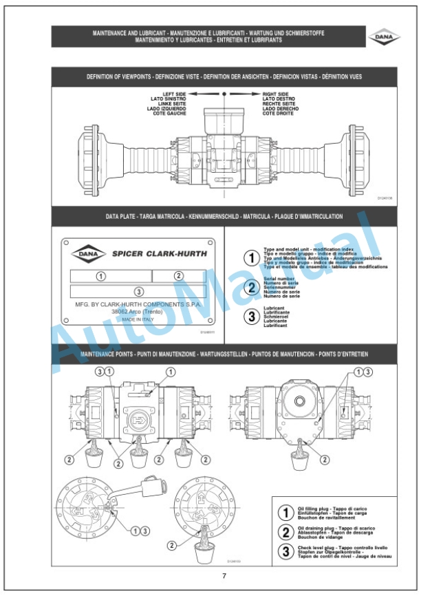
- 22.1. Suppliers documentation
- 22.2. Axle
- 22.3. Axle
- 22.4. Axle
- 22.5. Axle
- 22.6. Axle
- 22.7. Axle
- 22.8. Axle
- 22.9. Axle
- 22.10. Axle
- 22.11. Axle
- 22.12. Axle
- 22.13. Axle
- 22.14. Axle
- 22.15. Axle
- 22.16. Axle
- 22.17. Axle
- 22.18.
- 22.19.
- 23. Circuit diagrams
- 23.1. Circuit diagrams
- 23.2. S/N Wiring diagram 582 702 07
- 23.3. S/N Wiring diagram 582 702 07
- 23.4. S/N Wiring diagram 582 702 07
- 23.5. S/N Wiring diagram 582 702 07
- 23.6. S/N Wiring diagram 582 702 07
- 23.7. S/N Wiring diagram 582 702 07
- 23.8.
- 23.9. S/N Wiring diagram 582 702 32
- 23.10. S/N Wiring diagram 582 702 32
- 23.11. S/N Wiring diagram 582 702 32
- 23.12. S/N Wiring diagram 582 702 32
- 23.13.
- 23.14. S/N Wiring diagram 582 702 39
- 23.15. S/N Wiring diagram 582 702 39
- 23.16. S/N Wiring diagram 582 702 39
- 23.17. S/N Wiring diagram 12
- 23.18. S/N Wiring diagram 12
- 23.19. S/N Wiring diagram 12
- 23.20. S/N Wiring diagram 12
- 23.21. S/N Wiring diagram 12
Bomag Service Manual PDF
Bomag Service Manual PDF
Bomag Service Manual PDF
Bomag BC 572 RB Refuse Compactor Electric, Hydraulic Schematics Diagram 101570631001 – 101570631163
Bomag Service Manual PDF
Bomag Service Manual PDF
Bomag BC 462 EB Refuse Compactor Electric, Hydraulic Schematics Diagram 101930061001 – 101930061001
Bomag Service Manual PDF
Bomag Service Manual PDF
Bomag BC 463 RB-3 Refuse Compactor Electric Schematics Diagram 101930121001 – 101930129999
Bomag Service Manual PDF
Bomag BC 462 RB Refuse Compactor Electric, Hydraulic Schematics Diagram 101930031001 – 101930031042
Bomag Service Manual PDF
Bomag BC 473 RB-3 Refuse Compactor Electric Schematics Diagram 101930131001 – 101930139999
Bomag Service Manual PDF
Bomag BC 462 RB Refuse Compactor Electric, Hydraulic Schematics Diagram 101930071001 – 101930071002

