Claas ARION 640 630 620 610 600 (A19) Tractor Repair Manual DE
$300.00
- Model: ARION 640 630 620 610 600 (A19) Tractor
- Type Of Manual: Repair Manual
- Language: DE
- Format: PDF(s)
- Size: 253 MB
File List:
– Size(0.2 MB) 5.12.2009.pdf
– Size(0.8 MB) 5.12.2009.pdf
– Size(0.9 MB) 5.12.2009.pdf
– Size(10.9 MB) 4.9.2012.pdf
– Size(11 MB) 5.12.2009.pdf
– Size(13.1 MB) 5.12.2009.pdf
– Size(13.6 MB) 3.22.2013.pdf
– Size(14.3 MB) 3.6.2015.pdf
– Size(15 MB) 9.19.2012.pdf
– Size(2 MB) 6.24.2013.pdf
– Size(20.4 MB) 9.26.2012.pdf
– Size(28.5 MB) 10.14.2013.pdf
– Size(3.2 MB) 5.12.2009.pdf
– Size(37.4 MB) 1.21.2013.pdf
– Size(38.5 MB) 3.6.2015.pdf
– Size(39.2 MB) 1.21.2013.pdf
– Size(5.3 MB) 5.12.2009.pdf
– Size(96.8 MB) 9.26.2012.pdf
Size(0.2 MB) 5.12.2009.pdf
Table of Content:
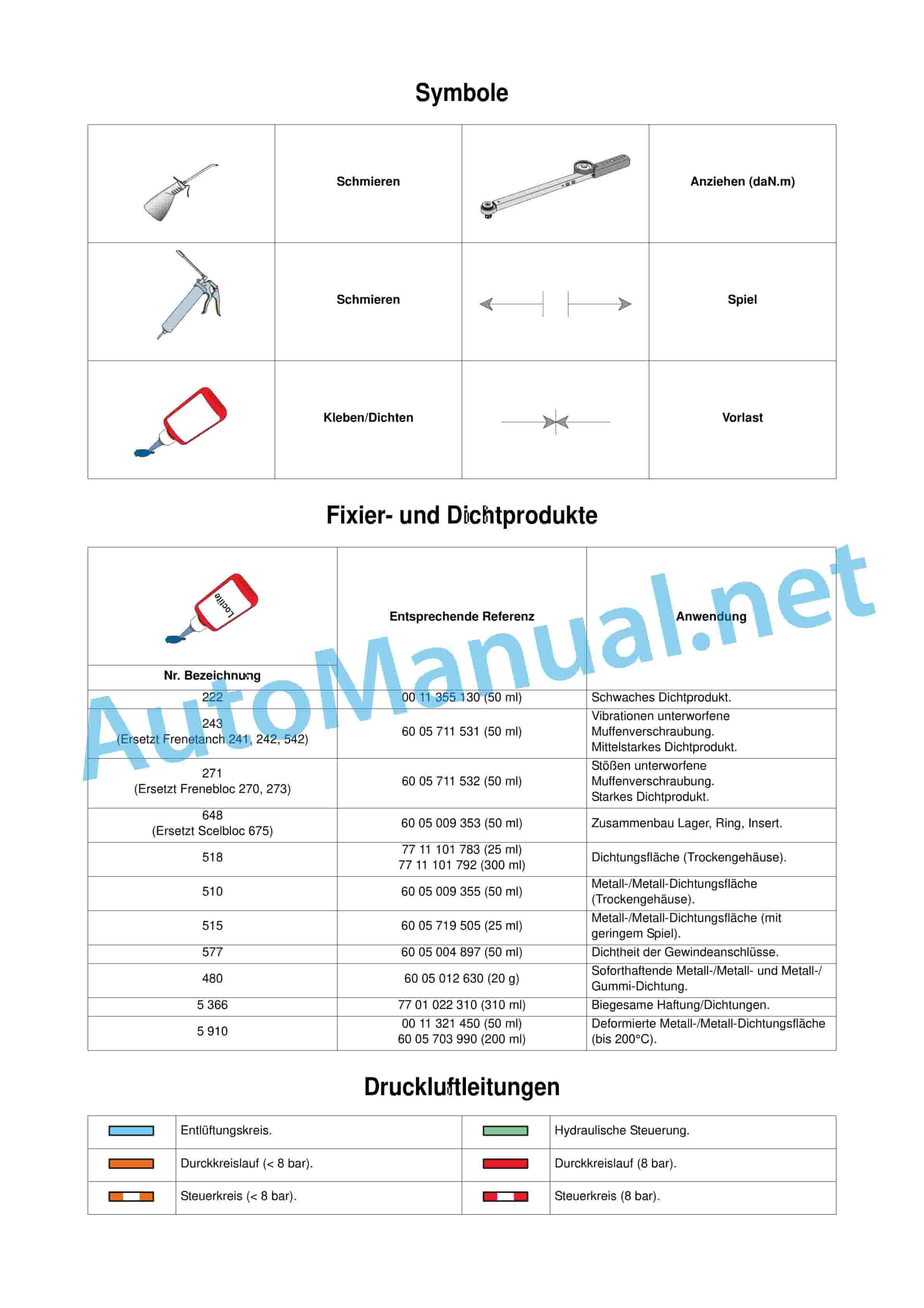
2 fixing and sealing products
3 compressed air li0
1.8 00 1135 452 0
1.9 00 1136 081 0
1.10 00 1136 138 0
1.11 00 1138 248 0
1.12 00 1138 249 0
1.13 60 0500 531 0
1.14 60 0500 550 4
1.15 60 0500 550 7
1.16 60 0500 550 9
1.17 60 0500 551 0
1.18 60 0500 632 0
1.19 60 0500 653 4
1.20 60 0500 653 5
1.21 60 0500 653 6
1.22 60 0500 653 7
1.23 60 0500 653 8
1.24 60 0500 653 9
1.25 60 0500 654 9
1.26 60 0500 655 0
1.27 60 0500 655 1
1.28 60 0500 655 2
1.29 60 0500 655 5
1.30 60 0500 655 9
1.31 60 0500 656 0
1.32 60 0500 656 1
1.33 60 0500 658 3
1.34 60 0500 658 6
1.35 60 0500 551 7
1.36 60 0500 552 0
1.37 60 0500 552 8
1.38 60 0500 553 1
1.39 60 0500 553 2
1.40 60 0500 557 3
1.41 60 0500 557 6
1.42 60 0500 557 7
1.43 60 0500 559 4
1.44 60 0500 559 5
1.45 60 0500 571 8
1.46 60 0500 572 6
1.47 60 0500 573 4
1.48 60 0500 615 3
1.49 60 0500 615 5
1.50 60 0500 670 3
1.51 60 0500 670 4
1.52 60 0500 675 8
1.53 60 0503 324 9
1.54 60 0503 325 0
1.55 60 0571 280 0
1.56 60 0571 297 1
1.57 77 0002 966 5
1.58 77 0002 966 6
1.59 77 0002 966 7
1.60 77 0005 436 1
1.61 77 0006 523 6
1.62 77 0138 800 8
1.63 77 0138 803 1
1.64 77 0138 804 7
1.65 77 0138 808 4
1.66 77 0138 811 0
1.67 77 0138 811 1
1.68 77 0138 812 7
1.69 77 0138 818 0
1.70 77 0138 890 7
1.71 77 1113 251 7
Size(0.9 MB) 5.12.2009.pdf
Table of Content:
1.1 J1 – Attachment points
2 J1_001-002_ARION_640-510_REPARATION_02A.pdf
2.1 Attachment points
Size(10.9 MB) 4.9.2012.pdf
Table of Content:
1 D0 FRONT AXLE – 4 WHEEL DRIVE
1.1 D1 RIGID FRONT AXLE
1.2 D2 SUSPENSION FRONT AXLES
1.3 D3 4 WHEEL DRIVE
Size(11 MB) 5.12.2009.pdf
Table of Content:
1.1 E1 – General
1.2 E2 – Hydraulic supply
1.3 E3 – rear power lift
1.4 E4 – control va10_REPARATION_DE.pdf
2.1 E1 GENERAL
3 E1_003_006_ARION_640-510_REPARATION_A3_DE.pdf
3.1 Specific torques and sealants
3.2 Specific torques and sealants
4 E1_007_008_ARION_640-510_REPARATION_DE.pdf
4.1 3 stage control valve option “ZF” and flow controller
4.2 4 stage control valve option “KO”, “ZF” and flow controller
5 E2_001_008_ARION_640-510_REPARATION_DE.pdf
5.1 E2 hydraulic supply
6 E2_009_010_ARION_640-510_REPARATION_A3_DE.pdf
6.1 Position of the components on the cover left and right
6.2 Exploded view of the lid left and right
7 E2_011_022_ARION_640-510_REPARATION_DE.pdf
7.1 Removing the priority valve block
7.2 Removing the right cover
7.3 Removing the 5 bar safety valve
7.4 Reinstalling the 5 bar safety valve
7.5 Removing the variable displacement pump
7.6 Reinstalling the variable displacement pump
7.7 Reinstalling the right cover
7.8 Reinstalling the priority valve block
7.9 Removing the left cover
7.10 Reinstalling the left cover
7.11 Removing the oil spray pump
7.12 Reinstalling the oil spray pump
7.13 Replacing the pump seals
8 E3_001_008_ARION_640-510_REPARATION_DE.pdf
8.1 E3 rear power lift
9 E4_001_022_ARION_640-510_REPARATION_DE.pdf
9.1 E4 control valve
10 E5_001_018_ARION_640-510_REPARATION_DE.pdf
10.1 E5 Steering
Size(13.1 MB) 5.12.2009.pdf
Table of Content:
1 C1 rear axle
1.1 Rear axle
1.2 Measurements and controls
1.3 Differential
1.4 Rear axle funnel
1.5 Lubrication hydraulic unit
1.6 Measurement data sheet
2 C0_001-008_ARION_640-510_DIAGNOSTIC_TDM_DE.pdf
2.1 Content
3 C2_001-046_ARION_640-510_DIAGNOSTIC_DE.pdf
3.1 C2 rear PTO
4 C3_001-004_ARION_640-510_DIAGNOSTIC_DE.pdf
4.1 C3 handbrake
5 C5_001-016_ARION_640-510_DIAGNOSTIC_DE.pdf
5.1 General description
5.2 Measurements and controls
5.3 Hydraulic part
5.4 Electronic part
5.5 Data sheets
6 C6_001-004_ARION_640-510_DIAGNOSTIC_DE.pdf
6.1 General description
7 C7_001-038_ARION_640-510_DIAGNOSTIC_DE.pdf
7.1 General description
7.2 Generation of compressed air energy
7.3 Pneumatic brake
7.4 Data sheets
8 C4_001-008_ARION_640-510_DIAGNOSTIC_DE.pdf
8.1 General description
8.2 Measurements and controls
8.3 Hydraulic part
8.4 Data s?(13.6 MB) 3.22.2013.pdf
Table of Content:
1.1 E1 – Hydraulics
1.2 E2 – rear power lift
1.3 E3 – Control valves
1.4 E4 – Steering
2 E1_001_002_ARION_640-510_DIAGNOSTIC_DE.pdf
2.1 E1 Hydraulic
3 E1_003_006_ARION_640-510_DIAGNOSTIC_A3_DE.pdf
3.1 Hydraulic diagram
4 E1_007_068_ARION_640-510_DIAGNOSTIC_DE.pdf
4.1 Claas Component Number
4.2 Hydraulics 60 l/Min
4.3 Hydraulics 110 l/min
5 E2_001_016_ARION_640-510_DIAGNOSTIC_DE.pdf
5.1 E2 rear power lift
6 E3_001_024_ARION_640-510_DIAGNOSTIC_DE.pdf
6.1 E3 control valves
7 E4_001_020_ARION_640-510_DIAGNOSTIC_DE.pdf
7.1 E4 steering
Size?(14.3 MB) 3.6.2015.pdf
Table of Content:
1.1 A1 – Motor
2 A1_001-004_ARION_640-510_DIAGNOSTIC_DE.pdf
2.1 A1 Motor
3 A1_005-006_ARION_640-510_DIAGNOSTIC_A3_DE.pdf
3.1 Tightening torques and sealing products
4 A1_007-088_ARION_640-510_DIAGNOSTIC_DE.pdf
4.1 Injection data sheets
4.2 Data sheets
4.3 Injection data sheets
4.4 Data sheets
4.5 Electronic injection
4.6 Measurement and control
4.7 Data sheets
4.8 Inlet and outlet
4.9 Measurement and control
4.10 Data sheets
4.11 Starting
4.12 Preheating system
4.13 Lubrication
4.14 Measurement and control
4.15 Data sheets
4.16 Cooling
4.17 Measurement and control
4.18 Control and automation
4.19 Protective devices and automation
4.20 Additional power control
Size(15 MB) 9.19.2012.pdf
Table of Content:
1 B1_001-002_ARION_640-510_REPARATION_DE.pdf
1.1 B1 General
2 B1_003-008_ARION_640-510_REPARATION_A3_DE.pdf
2.1 Most important settings
2.2 Tightening torques and sealing products
2.3 Pairs and sealed specific workflow control
2.4 Expansion
3 B5_001-006_ARION_640-510_REPARATION_DE.pdf
3.1 Exploded view
3.2 Removing/reinstalling the unit
3.3 Removal/adjustment and reinstallation of the switching device
3.4 Setting the shift fork
4 B6_001-006_ARIONON_DE.pdf
4.1 Exploded view
4.2 Removing/reinstalling the unit
4.3 Removal/adjustment and reinstallation of the switching device
4.4 Setting the shift fork
5 B0_001-004_ARION_640-510_REPARATION_TDM_DE.pdf
5.1 Content
6 B2_001-020_ARION_640-510_REPARATION_DE.pdf
6.1 B2 Hexashift
7 B3_001-020_ARION_640-510_REPARATION_DE.pdf
7.1 B3 REVERSHIFT
8 B4_001-020_ARION_640-510_REPARATION_DE.pdf
8.1 Tool for self-production
8.2 Exploded view
8.3 Removing the switching group module
8.4 Removing the switching group module
8.5 Removing the primary line
8.6 Reinstalling the primary line
8.7 Removing the secondary line
8.8 Reinstalling the secondary line
8.9 Adjusting the shafts in the housing
8.10 Measuring the shaft clearances in the housing
8.11 Reinstalling the switching group module
Size(2 MB) 6.24.2013.pdf
2.3 “Cebis” terminal (MFT A30)
2.4 List of error codes
3 G2 control panel WLP
3.1 General description
3.2 Work lights
3.3 Cabin lighting
3.4 Rotating lights.
3.5 De-icing
Size(20.4 MB) 9.26.2012.pdf
Table of Content:
1.1 C1 – General
1.2 C2 – drive bevel gear bevel gearbox
1.3 C3 – Differential
1.4 C4 – PTO shaft
1.5 C5 – Handbrake
1.6 C6 – service brake 40 and 50 km/h
1.7 C7 – Rear axle funnel
2 C1_001-002_ARION_640-510_REPARATION_DE.pdf
2.1 C1 General
3 C1_003_004_ARION_640-510_REPARATION_A3_DE.pdf
3.1 Longitudinal section view of the rear axle (version 50 km/h)
3.2 View in cross section of the rear axle GPA 23 version 40 and 50 km/h
4 C1_005-008_ARION_640-510_REPARATION_DE.pdf
4.1 Rear axle funnel SHD
4.2 Rear axle funnel SHD
4.3 Tool for4_ARION_640-510_REPARATION_DE.pdf
7.1 Rear PTO clutch
7.2 Upper rear power take-off shaft
7.3 Lower rear power take-off shaft
7.4 Encoder and PTO shaft operation
7.5 Proportional PTO
8 C5_001-018_ARION_640-510_REPARATION_DE.pdf
8.1 Exploded View
8.2 Expansion
8.3 Replacement
8.4 Setting mechanism
8.5 Setting the shift fork
8.6 Handbrake 50 km/h translation
9 C6_001-024_ARION_640-510_REPARATION_DE.pdf
9.1 Service brake 40 km/h translation
9.2 Service brake 50 km/h translation
9.3 Brake line transmission 40 km/h
9.4 Brake line transmission 50 km/h
10 C7_001-022_ARION_640-510_REPARATION_DE.pdf
10.1 Rear axle funnel HD
10.2 Rear axle funnel SHD
Size”Hexashift”
1.3 B3 – “REVERSHIFT”
1.4 B4 – Games robotises
1.5 B5 – reduction gear
1.6 B6 – Automatic
2 B1_001-008_ARION_640-510_DIAGNOSTIC_DE.pdf
2.1 B1 General description
3 B1_009-010_ARION_640-510_DIAGNOSTIC_A3_DE.pdf
3.1 Sectional view GBA 25
4 B5_001-018_ARION_640-510_DIAGNOSTIC_DE.pdf
4.1 B5 reduction gear
5 B6_001-030_ARION_640-510_DIAGNOSTIC_DE.pdf
5.1 B”Hexashift”
7 B3_001-044_ARION_640-510_DIAGNOSTIC_DE.pdf
7.1 B3 REVERSHIFT
8 B4_001-038_ARION_640-510_DIAGNOSTIC_DE.pdf
8.1 B4 Robotized switching groups
Size(3.2 MB) 5.12.2009.pdf
Table of Content:
1.1 H1 – Raising the cabin
1.2 H2 – Air conditioning/heating
2 H1_001-016_ARION_640-510_REPARATION_DE.pdf
2.1 H1 Raising the cabin
3 H2_001-008_ARION_640-510_REPARATION_DE.pdf
3.1 H2 air conditioning/heating
Size(37.4 MB) 1.21.2013.pdf
Table of Content:
1 ELECTRICAL – NON-UNIFIED ARCHITECTURE
1.1 HELP USING TECHNICAL SUPPORT
1.2 F0 – GENERAL
1.3 F1 – FUNCTIONAL CIRCUIT DIAGRAMS
1.4 F2 – ELECTRICAL SYSTEM
1.5 F3 – INSTALLATION PLANS
Size(38.5 MB) 3.6.2015.pdf
Table of Content:
1.1 A1 – GENERAL
1.2 A2 – Cylinder head and valves
1.3 A3 – cylinder liners, pistons, connecting rods
1.4 A4 – flywheel, – Lubrication circuit
2 A1_001-002_ARION_640-510_REPARATION_02A.pdf
2.1 A1 GENERAL
3 A1_003_004_ARION_640-510_REPARATION_A3_02A.pdf
3.1 Specific torques
4 A1_005-006_ARION_640-510_REPARATION_DE.pdf
4.1 Wedging between oil pan / front axle frame
5 A2_001-038_ARION_640-510_REPARATION_DE.pdf
5.1 A2 cylinder head and valves
6 A3_001-022_ARION_640-510_REPARATION_02A.pdf
6.1 A3 cylinder liners, pistons, connecting rods
7 A5_001-024_ARION_640-510_REPARATION_DE.pdf
7.1 Bore dimension of the camshaft ring
7.2 Measuring the axial play of the camshaft
7.3 Measuring the diameters of the camshaft ring and pins
7.4 Measuring the cam height
7.5 Measuring the axial play of the freewheel gear
7.6 Measuring the backlash of the camshaft drive gears
7.7 Checking the gears and locking plates of the balance shafts
7.8 Measuring the axial play of the balance shaft (4-cylinder engine)
7.9 Checking and measuring the balance shaft rings and journals
7.10 Removing the water pump
7.11 Dismantling the water pump
7.12 Mounting the water pump
7.13 Reinstalling the water pump
7.14 Dismantling the front cover
7.15 Removing the pressure regulator
7.16 Reinstalling the pressure regulator.
7.17 Removing the camshaft and wear ring
7.18 Reinstalling the camshaft and wear ring
7.19 Removing the balance shafts
7.20 Removal and installation of the balance shaft rings
7.21 Removing and installing the balance shaft gears.
7.22 Removing the front plate
7.23 Reinstalling the front panel
7.24 Reinstalling the balance shafts
7.25 Motor control setting
7.26 Reinstalling the valve control housing
8 A7_001-008_ARION_640-510_REPARATION_DE.pdf
8.1 Removing the oil filter and bracket
8.2 Installing the oil filter and bracket.
8.3 Removing the oil cooler
8.4 Installation of the oil cooler
8.5 Attaching the engine oil pan
8.6 Removing the oil pump
8.7 Reinstalling the oil pump
8.8 Installation of the engine oil pan
9 A4_001-016_ARION_640-510_REPARATION_DE.pdf
9.1 Measuring the inner diameter of the crankshaft journals and bearings
9.2 Measuring the width of the stop pins and bearings
9.3 Checking the axial play of the crankshaft
9.4 Removing the damper disc
9.5 Reinstalling the damper disc
9.6 Removing the front bearing bush seal
9.7 Reinstalling the front bearing bush seal
9.8 Removing the engine flywheel
9.9 Reinstalling the engine flywheel
9.10 Removing the rear bearing bush seal
9.11 Reinstalling the rear bearing bush seal
9.12 Removing the flywheel housing
9.13 Reinstalling the flywheel housing
9.14 Removing the locking wheel
9.15 Reinstalling the locking wheel
9.16 Removing the crankshaft gear
9.17 Reinstalling the crankshaft gear
9.18 Removing the crankshaft bearings and the crankshaft
9.19 Reinstalling the crankshaft bearings and the crankshaft
10 A6_001-012_ARION_640-510_REPARATION_DE.pdf
10.1 Removing the supply pump
10.2 Reinstalling the supply pump
10.3 Expansion of the high-pressure common rail
10.4 Reinstalling the high-pressure common rail
10.5 Removing the flow controller
10.6 Reinstalling the flow regulators
10.7 Removing the pressure limiter
10.8 Reinstalling the pressure limiter
10.9 Removing the high pressure pump
10.10 Reinstalling the high pressure pump
10.11 Removing the high pressure pump filter
10.12 Reinstalling the high pressure pump filter
10.13 Removing the solenoid valve
10.14 Reinstalling the solenoid valve
10.15 Removing the electronic injectors
10.16 Reinstalling the electronic injectors
Size(39.2 MB) 1.21.2013.pdf
Table of Content:
1 ELECTRICAL – FROM NO. A1801259, A1902417
1.1 HELP USING TECHNICAL SUPPORT
1.2 F0 – GENERAL
1.3 F1 – FUNCTIONAL CIRCUIT DIAGRAMS
1.4 F2 – CONNECTION PLANS
1.5 F3 – INSTALLATION PLANS
Size(5.3 MB) 5.12.2009.pdf
Table of Content:
1 On of movement
3.1 Overview
3.2 Schematic representation
4 MECHANICAL PART
4.1 Overview
4.2 Differential front
5 D3_001-014_ARION_510-640_DIAGNOSTIC_DE.pdf
5.1 Overview
5.2 Functional diagram
5.3 Schematic representation
5.4 Measurements and controls
5.5 MECHANICAL PART
5.6 Hydraulic part for control
5.7 Electronic part
5.8 Data sheets
6 D4_001-014_ARION_640-510_DIAGNOSTIC_DE.pdf
6.1 Overview
6.2 Property
6.3 Functional diagram
6.4 Measurements and controls
6.5 MECHANICAL PART
6.6 Hydraulic part for control
6.7 Electronic part
6.8 Lubrication hydraulic unit
6.9 Data sheets
7 D0_000-006_ARION_640-510_DIAGNOSTIC_TDM_DE.pdf
7.1 Content
8 D2_001-018_ARION_640-510_DIAGNOSTIC_DE.pdf
8.1 General description
8.2 Checking the front axle suspension
8.3 Transmission of movement
8.4 Proactiv suspension
8.5 Data sheets
Size(96.8 MB) 9.26.2012.pdf
Table of Content:
1.bis – C.I.S.
2 B1_001-048_ARION_640-510_CCN_METHOD_DE.p”Auto 5″
2.4 Water Sensor
2.5 Hall sensor
2.6 Inductive encoder with variable magnetic resistance
2.7 Encoder with flexible plate
2.8 Magneto-elastic encoder
2.9 Pressure sensor (rheostat)
2.10 Temperature sensor (hot conductor)
2.11 Supply circuit magnetic switch
2.12 Detection contactor
2.13 Earth contact
2.14 Proportional solenoid valve.
2.15 On/Off controlled solenoid valve.
2.16 Control element
2.17 Electric motor
2.18 Photoresistor
2.19 Potentiometer
2.20 Radar
2.21 Relay
2.22 Resistance
2.23 Solenoid
3 A1_001-036_ARION_640-510_CCN_ELECTRONIQUE_DE.pdf
3.1 Electronics Cebis
3.2 Electronics C.I.S.
3.3 Engine speed specification
3.4 Display of the engine speed Cebis”Revershift” output)
3.9 Travel speed Cebis
3.10 Travel speed C.I.S.
3.11 CLAAS “A6”
4.2 Engine module “ENG A15″”
4.3 Terminal module “Cebis A30”
4.4 Gearbox module “TR1 A57-1”
4.5 Gearbox module “TR2 A57-2”
4.6 Gearbox module “TR3 A57-3”
4.7 Rear power lift module “A58″
4.8 Electric directional control valve module Ventil-x?”HYD A60”
4.10 Module external functions “EXT A62”
4.11 Multifunctional armrest module “MFA A100”
4.12 Dashboard and CAN network communication module “DBD A101”
4.13 Module sprung front axle “A 102”
4.14 Module work light “WLP A104”
4.15 Turbocharger module “A109”
4.16 Display module for manual transmission “DSP A124”
4.17 Intake air temperature sender “B1”
4.18 Fuel pressure sender “B42”
4.19 Fuel temperature sensor “B44”
4.20 Coolant temperature sender “B45”
4.21 Intake air pressure sensor “B51”
4.22 Cabin air conditioning temperature sensor “B86”
4.23 Temperature sensor of the circulating air conditioning system “B87”
4.24 Outside air temperature sensor of the air conditioning system “B88”
4.25 Transmission oil temperature sender “B123”
4.26 Rear hitch position sensor “B139”
4.27 PTO shaft speed sensor “B142”
4.28 Left “B144-1” and right “B144-2” force sensor
4.29 Temperature sensor cooled exhaust gases “B221”
4.30 Cool intake air temperature sensor “B222”
4.31 Mixed intake air temperature sensor “B223”
4.32 Solar panel “B224”
4.33 Sensor for water in fuel “B225”
4.34 Turbocharger speed sensor “B226”
4.35 Sensor for the theoretical speed “B227”
4.36 Engine speed sensor (on clutch bell PTO shaft) “B228-1”
4.37 The engine speed sensor (on input shaft gearbox) “B228-2”
4.38 Intermediate speed sensor gearbox “B229”
4.39 Actual vehicle speed sensor (radar) “B230”
4.40 Crankshaft position and engine speed sensor “B231”
4.41 Distributor position and engine speed sensor “B232”
4.42 The brake pressure sensor “B233”
4.43 Axle suspension position sensor “B234”
4.44 Glow plug relay “K1”
4.45 Actuator valve “EGR M38”
4.46 Driven heating valve “M40”
4.47 Recycling actuator “M41”
4.48 Fuel level “R35”
4.49 Angle position sensor accelerator pedal “R71”
4.50 Hand throttle control “R72”
4.51 Angle position sensor pedal “R73”
4.52 Operation “Drivestick “R74”
4.53 Cross control directional control valve “R75”
4.54 Line control directional control valve “R76”
4.55 Potentiometer for setpoint power lift “R77”
4.56 Pre-glow plug “R78”
4.57 Switch 4 wheel drive “S1”
4.58 The ignition key “S64”
4.59 Differential lock switch “S94”
4.60 PTO shaft on/off contactor “S114”
4.61 Torque converter switch “Revershift S171”
4.62 Automatic PTO switch “S172”
4.63 PTO shaft brake switch “S173”
4.64 Switch “CLAAS Sequence Management S177”
4.65 Memory contactor motor speed “S178” and “S179”
4.66 Contactor for setting the gearbox to neutral position “S180”
4.67 Contactor for adjusting motor speed “S188” and “S189”
4.68 Switch of the “Hexactiv S192” function
4.69 Switch for work/transport mode “S193”
4.70 Hydraulic switch “on/off S194”
4.71 Switch of the suspended front axle “S195”
4.72 Contactor for switching rear PTO on/off “U50”
4.73 Rear PTO emergency stop contactor “U53”
4.74 Rear switch of the directional control valves “U55” and “U56”
4.75 Rear switch of the rear power lift “U57”, “U58”
4.76 Control panel of the power lift “V22”
4.77 Electronic adaptation board “PAE V24”
4.78 Solenoid valve 4 wheel drive “Y1”
4.79 Differential lock solenoid valve “Y105”
4.80 Electronic Injector “Y320”
4.81 Inlet valve “Y321”
4.82 Rear PTO clutch valve “Y325”
4.83 Solenoid valves of the “Revershift”, “Y327” and “Y328”
4.84 Solenoid valve braking “Y329”
4.85 Solenoid valve for supplying the suspension “Y333”
4.86 Solenoid valve for powershift stages “Y335”
4.87 Rear power lift raising/lowering solenoid valve “Y336”, “Y337”
4.88 PTO brake solenoid valve “Y338”
4.89 Solenoid valve for robotized group “Y339”
4.90 solenoid valve pneum. Brake “Y340”
4.91 Solenoid valve pneum. Brake “Y340”
4.92 Solenoid valve for dosing (high pressure pump) “Y344”
4.93 Contactor for presence detection “Z5”
4.94 Contactor for handbrake “Z12”
4.95 Air conditioning gas pressure switch “Z21”
4.96 Air conditioning thermostat “Z24”
4.97 Pressure switch engine oil “Z42”
4.98 Air filter clogging contactor “Z69”
4.99 Air filter clogging contactor “Z69”
4,100 Brake fluid level switch “Z76”
4.101 Pressure switch for clogging of the high pressure filter (60 l/min) “Z102”
4.102 Pressure switch for clogging of the high pressure filter (110 l/min) “Z102”
4.103 Left brake pedal switch “Z126”
4.104 Right brake pedal switch “Z127”
4.105 Switch group “Creep speed” “Z150”
4.106 Pressure switch of the lubrication and feed circuit “Z151”
4.107 Pedal switch in lower position “Z152”
4.108 Switch group “Z153”
4.109 Switch economical PTO shaft 540 “Z159”
4.110 PTO switch 1,000 rpm “Z160”
4.111 PTO switch 540 rpm “Z161”
4.112 Switch proportional PTO shaft “Z162”
4.113 Thermal switch high pressure oil filter (110 l/min) “Z181”
4.114 Pressure regulator intake circuit (60 l/min) “Z183”
4.115 Pressure contact transmission control circuit (60 l/min) “Z184”
4.116 Pressure contact transmission control circuit (110 l/min) “Z184”
5 B0_000-004_ARION_640-510_CCN_METHOD_TDM_DE.pdf
5.1 Content
John Deere Repair Technical Manual PDF
John Deere Diesel Engines POWERTECH 2.9 L Component Technical Manual CTM126 Spanish
John Deere Repair Technical Manual PDF
John Deere Diesel Engines PowerTech 4.5L and 6.8L – Motor Base Technical Manual 07MAY08 Portuguese
John Deere Repair Technical Manual PDF
John Deere Application List Component Technical Manual CTM106819 24AUG20
John Deere Repair Technical Manual PDF
John Deere POWERTECH E 4.5 and 6.8 L Diesel Engines TECHNICAL MANUAL 25JAN08
John Deere Repair Technical Manual PDF
John Deere Repair Technical Manual PDF
John Deere Transmission Control Unit Component Technical Manual CTM157 15JUL05
John Deere Repair Technical Manual PDF
John Deere Repair Technical Manual PDF
John Deere Repair Technical Manual PDF
John Deere 18-Speed PST Repair Manual Component Technical Manual CTM168 10DEC07

