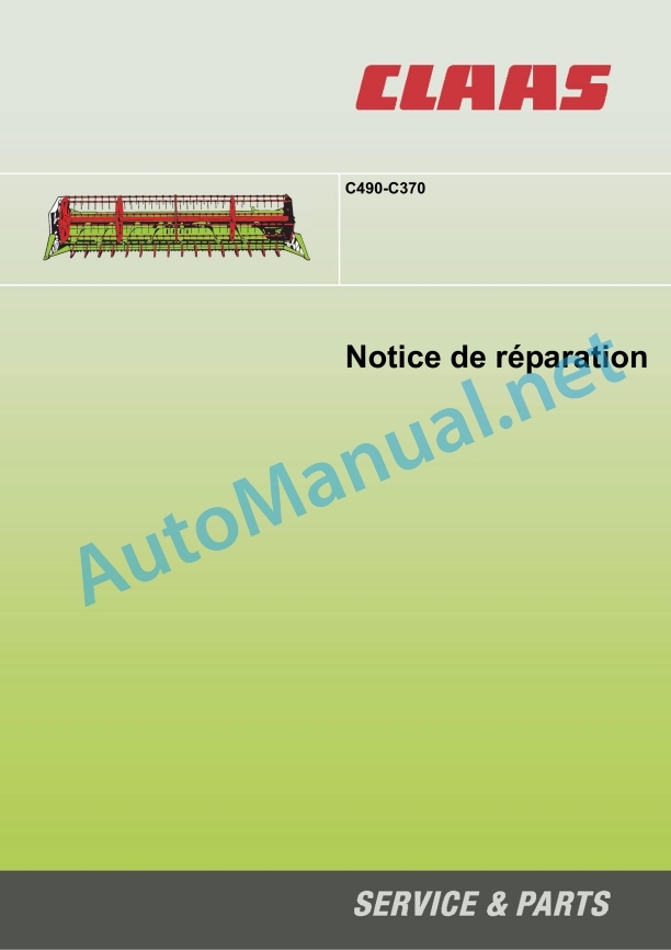
Claas C490-C300 Lexion Tucano (527) Combines Repair Manual FR
$300.00
- Model: C490-C300 Lexion Tucano (527) Combines
- Type Of Manual: Repair Manual
- Language: FR
- Format: PDF(s)
- Size: 8.7 MB
File List:
00 0290 396 0.pdf
00 0290 396 0.pdf:
Contents
Introduction
General advice
Use of the instructions
Validity of the notice
General repair tips
Technical information
Origin of the failure
Spare parts
Gearboxes
Tension steel roller chains
Tapered Ring Fittings
Heel pin assemblies
Self-locking screws with micro-encapsulated glue
Liquid screw brake
Clamp ring bearing
Clamping sleeve bearing
Screwed connections with cutting ring on hydraulic lines
Progressive ring fittings on hydraulic lines
Bicone ring screw connections on hydraulic lines
Hydraulic flexible lines
Tips for an economical repair
Tightening torques
Tightening torque for metric adjustment thread
Tightening torques for fine metric threads
Tightening torques for hydraulic connections with cutting ring DIN 3861
Tightening torques for hydraulic connections and air conditioning connections with bicone ring and O-ring DIN 3865
Tightening torques for hydraulic threaded couplings DIN 3901
Tightening torques for hydraulic threaded sleeve, direction adjustable ISO 6149-2 / ISO 11926-2 (3)
Tightening torques for hydraulic swivel screw connections
Tightening torques for hollow screws DIN 7643
Tightening torques for brake line screw connections
Tightening torques for tangent screw clamps
Technical characteristics
Lubricants
NCC declarations
CCN (CLAAS Component Number)
Electrical standard
Hydraulic standard
Security
General advice
Important
Marking of warnings and dangers
General safety and accident prevention regulations
Front implements and trailers
Adjustment and maintenance work
Hydraulic fluid poses a risk of injury
First aid measures
Lifting the machine using jacks
Turn off the machine
02 Gearbox / Clutch / Cardan shaft
02 60 Cardan shaft
Remove/disassemble the cardan shaft
Overview of the cardan shaft
Assemble and install the cardan shaft
08 Workouts
08 00 Training scheme
Training scheme
08 14 Intermediate shaft
Remove the intermediate shaft
Intermediate shaft overview
Install the intermediate shaft
09 Hydraulic system
09 15 Hydraulic lines
Overview of the front tool multiple coupling (8011)
09 20 Valves, gates
Overview of the reel adjustment distribution block
09 20 Special tool, valves
Extract the valve packing
Unscrew the iron core
Dismantle the sealing ring
20 Harvest feeding
20 15 Reel
Remove the reel
Install the reel
Remove the reel shaft bearing
Overview of reel shaft bearing
Install the reel shaft bearing
Reel RPM Sensor Overview (B017)
Overview of the reel height adjustment sensor (B039)
Remove the left side reel support arm
Install the left side reel support arm
Remove the right side reel support arm
Install the right side reel support arm
Remove the right side reel hub star
Overview of the right side reel hub star
Install the right side reel hub star
Remove the reel hub star in the center
Overview of reel hub star in center
Install the reel hub star in the center
Remove the left side reel hub star
Overview of the left side reel hub star
Install the left side reel hub star
Drop the command star
Overview of the command star
Install the command star
Remove the reel tine tube
Install the reel tine holder tube
Remove reel drive
Overview of reel drive, chain (K9)
Install the reel drive
Overview of drive sprocket, chain (K9)
Overview of output sprocket, chain (K9)
Remove the reel horizontal adjustment hydraulic cylinder (3016)
Overview of Reel Horizontal Adjustment Hydraulic Cylinder (3016)
Installation of the hydraulic cylinder for horizontal adjustment of the reel (3016)
Remove the left side reel height adjustment hydraulic cylinder (3015)
Overview of the hydraulic cylinder for height adjustment of the left side reel (3015)
Install the left side reel height adjustment hydraulic cylinder (3015)
Remove the right side reel height adjustment hydraulic cylinder (3014)
Overview of the hydraulic cylinder for height adjustment of the right side reel (3014)
Installation of the hydraulic cylinder for adjusting the height of the reel on the right side (3014)
Remove the hydraulic reel drive motor (2012)
Overview of the hydraulic reel drive motor (2012)
Install the hydraulic reel drive motor (2012)
21 Power group
21 40 Feed roller
Remove the feed roller
Install the feed roller
Remove the left side feed roller bearing
Left Side Feed Roller Bearing Overview
Install the left side feed roller bearing
Remove the right side feed roller bearing
Install the right side feed roller bearing
Remove the adjustment shaft
Overview of the adjustment shaft
Install the adjustment shaft
Remove the control shaft
Overview of the control shaft
Install the control shaft
Feed Roller Drive Overview, Chain (K6)
Remove the output sprocket, chain (K6) with friction torque limiter
Overview of output sprocket, chain (K6) with friction torque limiter
Install the output sprocket, chain (K6) with friction torque limiter
21 40 Special tool, feed roller
Remove/install feed roller bearing
Remove/install output sprocket, chain (K6) with friction torque limiter
23 Cutting unit
23 05 Cutting bar
Remove and disassemble swing gearbox
Oscillation Gearbox Overview
Assemble and install the oscillation gearbox
Overview of knife drive, belt (R1)
Overview of the belt tensioner pulley (R1)
Overview of reversing pulley, belt (R1)
Remove the driven pulley, belt (R1)
Overview of driven pulley, belt (R1)
Install the driven pulley, belt (R1)
21 23 Special tool, cutting unit
Disassemble/Assemble Oscillation Gearbox
Install the reversing pulley, belt (R1)
26 Ground guidance
26 05 AUTO CONTOUR
Overview of AUTO CONTOUR sensor caliper (B003 / B004)
80 Assembly parts / machine casing
80 10 Lock
Remove front implement lock
Front attachment lock overview
Install the front tool lock
CCN (CLAAS Component Number)
Alphabetical index
John Deere Repair Technical Manual PDF
John Deere Repair Technical Manual PDF
John Deere Application List Component Technical Manual CTM106819 24AUG20
John Deere Repair Technical Manual PDF
John Deere Repair Technical Manual PDF
John Deere 16, 18, 20 and 24HP Onan Engines Component Technical Manual CTM2 (19APR90)
John Deere Repair Technical Manual PDF
John Deere Repair Technical Manual PDF
John Deere Repair Technical Manual PDF
John Deere Repair Technical Manual PDF
John Deere Parts Catalog PDF
John Deere Tractors 7500 Parts Catalog CPCQ26568 30 Jan 02 Portuguese


