Claas Cam Pilot (B84) Digital Solutions Assembly Instruction EN
$50.00
- Model: Cam Pilot (B84) Digital Solutions
- Type Of Manual: Assembly Instruction
- Language: EN
- Format: PDF(s)
- Size: 52.1 MB
File List:
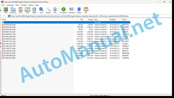
00 0018 562 0.pdf
00 0018 582 0.pdf
00 0019 422 0.pdf
00 0290 143 2.pdf
00 0295 903 1.pdf
00 0301 464 0.pdf
00 0303 656 1.pdf
00 1401 779 1.pdf
00 1403 186 1.pdf
00 1403 202 1.pdf
00 1420 077 0.pdf
00 2930 925 2.pdf
00 2993 707 0.pdf
00 2994 009 0.pdf
00 2994 044 0.pdf
00 0301 464 0.pdf:
PROFI CAM 3
Table of contents
1 Introduction
1.1 Notes on the manual
1.1.1 Validity of manual
1.1.2 Symbols and notices
1.2 Identifying warnings
1.2.1 Hazard signs
1.2.2 Signal word
1.3 Safety rules
1.3.1 Fitting and conversion work
2 Package list
2.1 Overview
2.1.1 PROFI CAM overview
2.1.2 Overview of special holder*
3 Mounting
3.1 Check list
3.1.1 Installing the PROFI CAM
3.2 Switching off and securing the machine
3.2.1 Switching off and securing the machine
3.3 Switch box
3.3.1 Installing the switch box
Mounting the switch box directly
Mounting the switch box with a bracket*
3.3.2 Connecting the switch box
3.4 Monitor
3.4.1 Observing the field of vision
3.4.2 Installing the monitor
3.4.3 Installing the monitor with base
3.4.4 Installing the monitor without a base
3.4.5 Installing the sun protection
3.4.6 Connecting the monitor electric connections
3.5 Camera
3.5.1 Determining the mounting position
3.5.2 Selecting the special bracket*
3.5.3 Installing the camera
3.5.4 Aligning the camera
3.5.5 Connecting the camera electrics
00 1401 779 1.pdf:
Table of contents
1 Introduction
1.1 General Information
1.1.1 Handling of manual
1.1.2 Validity
1.1.3 Warranty
2 Safety
2.1 General Information
2.1.1 Particularly important
2.1.2 Intended use
2.2 Safety rules
2.3 Safety instructions in this manual
2.3.1 Identification of warning and danger signs
3 Product description
3.1 CLAAS universal mounting kit
3.1.1 Description
4 Package list
4.1 Overview
4.1.2 Overview of electronics and accessories
4.1.3 Overview of safety components
4.1.4 Overview of cables
4.1.5 Open Center steering valve and fittings
4.1.6 LS steering valve and fittings
4.1.7 Lock-up valve unit and screw-in adapters
4.1.8 Camera
4.1.10 Overview of wiring loom / connections
Abbreviations of connections
5 Mounting
5.1 Hydraulic system
5.1.1 Installation variants
Non-reactive variant with Open Center
Reactive variant with Open Center
Non-reactive variant with LS
Reactive variant with LS
5.1.2 Hydraulic system installation
LS steering valve connections
OC steering valve connections
Lock-up valve unit connections
Installation examples
5.1.3 Steering angle sensor
Installation variants
Installation examples
5.2 Valve unit
5.2.1 UBM control unit
Installation examples
5.3 Sensor
5.3.1 Ground speed sensor
Installation examples
5.4 Safety devices
5.4.1 Seat contact switch
Installation examples
5.4.2 Overrider switch
Installation examples
5.5 Operating and control elements
5.5.1 Communicator
Installation examples
5.5.2 External activation
Installation examples
5.6 Camera
5.7 Cable routing
6 Technical terms and abbreviations
6.1 CAM PILOT
John Deere Repair Technical Manual PDF
John Deere Parts Catalog PDF
John Deere Tractors 7500 Parts Catalog CPCQ26568 30 Jan 02 Portuguese
New Holland Service Manual PDF
John Deere Repair Technical Manual PDF
John Deere Repair Technical Manual PDF
John Deere Repair Technical Manual PDF
John Deere Repair Technical Manual PDF
John Deere Repair Technical Manual PDF
John Deere Diesel Engines PowerTech 4.5L and 6.8L – Motor Base Technical Manual 07MAY08 Portuguese
John Deere Repair Technical Manual PDF
John Deere Application List Component Technical Manual CTM106819 24AUG20

