Claas Cutterbar Trailer 13,5M-7,7M (521) Combines Operator Manual EN
$50.00
- Model: Cutterbar Trailer 13,5M-7,7M (521) Combines
- Type Of Manual: Operator Manual
- Language: EN
- Format: PDF(s)
- Size: 20.0 MB
File List:
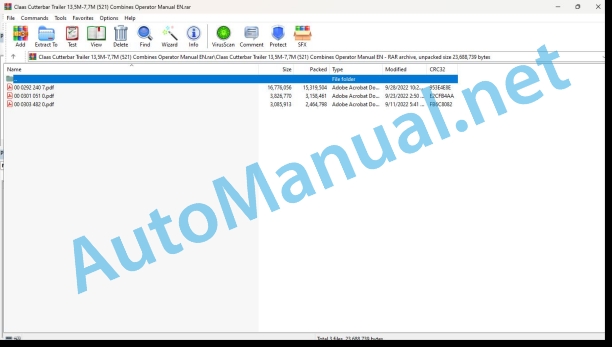
00 0292 240 7.pdf
00 0301 051 0.pdf
00 0303 482 0.pdf
00 0292 240 7.pdf:
1380 / 13501230 / 12001080 / 1050930 / 900770
Table of contents
1 Introduction
1.1 Notes on the manual
1.1.1 Validity of manual
1.1.2 Information about this Operator’s Manual
1.1.3 Symbols and notes
1.1.4 Qualified specialist workshop
1.1.5 Maintenance notes
1.1.6 Warranty notes
1.1.7 Spare parts and technical questions
1.2 Intended use
1.2.1 Intended use
1.2.2 Reasonably foreseeable misuse
2 Safety
2.1 Identifying warnings
2.1.1 Hazard signs
2.1.2 Signal word
2.2 Safety rules
2.2.1 Importance of Operator’s Manual
2.2.2 Requirements for all persons working with the machine
2.2.3 Children in danger
2.2.4 Hazard areas
2.2.5 Persons riding on the machine
2.2.6 Fitting a front attachment or hitching a transport trailer to the machine
2.2.7 Structural changes
2.2.8 Optional equipment and spare parts
2.2.9 Operation only following proper putting into operation
2.2.10 Technical condition
2.2.11 Danger from damage to the machine
2.2.12 Respecting technical limit values
2.2.13 Keeping the safety devices functional
2.2.14 Personal protective equipment
2.2.15 Wearing suitable clothing
2.2.16 Removing dirt and loose objects
2.2.17 Preparing the machine for road travel
2.2.18 Hazards when driving on the road and on the field
2.2.19 Parking the transport trailer safely
2.2.20 Unsuitable operating utilities
2.2.21 Safe handling of operating and auxiliary utilities
2.2.22 Environmental protection and disposal
2.2.23 Hot surfaces
2.2.24 Working on machine only after shutting it down
2.2.25 Maintenance operations and repair work
2.2.26 Raised machine parts and loads
2.2.27 Danger from welding work
2.3 Safety decals on the machine
2.3.1 Official licence plate
3 Machine description
3.1 Overview and method of operation
3.1.1 Overview of transport trailer
3.1.2 Function of transport trailer
3.2 Optional machine equipment
3.2.1 Short drawbar with brake system
3.2.2 Long drawbar with brake system
3.2.3 Long drawbar without brake system
3.3 Identification plates and identification numbers
3.3.1 Transport trailer identification plate
3.3.2 Drawbar identification plate
3.4 Information on the machine
3.4.1 Decal on the transport trailer
4 Technical specifications
4.1 Transport trailer
4.1.1 Dimensions
4.1.2 Weights
Permissible gross weight
4.1.3 Tyres
4.1.4 Lubricants
4.1.5 Hydraulic oil
5 Machine preparation
5.1 Unhitching and securing the transport trailer
5.1.1 Unhitching and securing the transport trailer
5.1.2 Arresting the transport trailer with a wheel chock
5.1.3 Fitting the wheel chocks on the transport trailer
5.2 Assembling the transport trailer
5.2.1 Prior to initial operation
5.2.2 Installing the drawbar
5.2.3 Installing the brake system
5.2.4 Adjusting the brake
Slackening off the turnbuckle
Checking if brake levers move freely
Adjusting the brake
Adjusting the turnbuckle
5.2.5 Fitting the lateral marking lights
5.2.6 Installing the mud guards
5.3 Adapting the transport trailer
5.3.1 Identifying the supports for the front attachment
5.3.2 Installing type A supports for VARIO / CERIO
Preparing the transport trailer
Fitting the front bracket
Adjusting the bracket
Preparing the support profile
Installing the swivelling supports
Installing the swivelling supports
Installing the support profile
5.3.3 Fitting the type A supports for VARIO
Preparing the transport trailer
Adjusting the bracket
Preparing the support profile
Installing the swivelling supports
Installing the support profile
5.3.4 Installing type A supports for MAXFLEX
Preparing the transport trailer
Adjusting the bracket
Preparing the support profile
Installing the swivelling supports
Installing the swivelling supports
Installing the support profile
5.3.5 Removing type A supports
5.3.6 Installing the type B supports
5.3.7 Removing the type B supports
5.3.8 Fitting type C supports for CORIO CONSPEED
Preparing the transport trailer
Removing the brackets
Fitting the brackets
Installing the support profile
5.3.9 Fitting type C supports for CORIO / CORIO CONSPEED
Preparing the transport trailer
Removing the brackets
Fitting the brackets
Fitting the rear bracket
Installing the stubble breaker bracket
Installing the support profile
5.3.10 Fitting type C supports for CONSPEED
5.3.11 Removing the type C supports
5.3.12 Installing type D supports
5.3.13 Removing the type D supports
5.3.14 Installing type E supports
5.3.15 Removing type E supports
5.3.16 Installing type F supports
5.3.17 Removing type F supports
5.3.18 Installing type G supports
5.3.19 Removing type G supports
5.3.20 Installing type H supports
5.3.21 Removing type H supports
5.3.22 Installing type I supports
Preparing the transport trailer
Fitting the brackets
Adjusting the bracket
Installing the support profiles
5.3.23 Removing type I supports
5.3.24 Fitting type J supports
Preparing the transport trailer
Fitting the brackets
Adjusting the bracket
Installing the swivelling supports
Installing the swivelling supports
Preparing the support profile
Preparing the support profile
Installing the support profile
5.3.25 Fitting type K supports
Fitting the brackets
Laying cables
Checking the Bowden cable
Adjusting the Bowden cable
5.3.26 Installing the swivelling support extensions
Installing the swivelling support extensions
Adjusting the swivelling support extension
5.3.27 Fitting the visibility kit for CONVIO FLEX / CONVIO
Installing the indicator on the front attachment
Installing the indicator on the front attachment
Installing the console on the transport trailer
Installing the console on the transport trailer
5.4 Loading the transport trailer
5.4.1 Loading and tying-down of transport trailer
6 Operation
6.1 Transporting the front attachment
6.1.1 Starting the transport
6.1.2 Ending the transport
6.1.3 Adjusting the support angle
Adjusting the swivelling support
6.1.4 Adjusting the swivelling support of the hydraulic type K supports
Preparing the pump
Adjusting the swivelling support
After pumping
6.1.5 Adjusting the swivelling support of the mechanical type B supports
6.1.6 Placing the front attachment on the transport trailer
6.1.7 Placing the front attachment on the transport trailer
6.1.8 Lifting the front attachment off of the transport trailer
6.2 Brake
6.2.1 Releasing the parking brake
6.2.2 Applying the parking brake
6.3 Hitch
6.3.1 Hitching the trailer to the towing vehicle
6.3.2 Unhitch the transport trailer from the towing vehicle
6.4 Electric system
6.4.1 Folding out the lighting bracket
6.4.2 Folding in the lighting bracket
6.4.3 Adjusting the lighting bracket length
6.4.4 Adjusting the lighting bracket width
7 Faults and remedies
7.1 Causes and remedies
7.1.1 Overview of faults on the transport trailer
7.1.2 Adjusting the drawbar support
7.1.3 Adjusting the brake shoes
7.1.4 Adjusting the brake levers to be parallel
8 Maintenance
8.1 Maintenance interval overview
8.1.1 After the first 10 operating hours
8.1.2 Every 50 operating hours
8.1.3 Every 100 operating hours
8.1.4 Every 250 operating hours or annually
8.1.5 Every 500 operating hours
8.1.6 Preserving the transport trailer
8.2 Lubrication plan
8.2.1 Grease the grease points every 50 operating hours
8.2.2 Grease the grease points every 100 operating hours
8.3 Chassis
8.3.1 Checking the wheel hub bearing play
8.3.2 Adjusting the wheel hub bearing play
8.3.3 Checking the tightening torque of wheel nuts
8.4 Brake
8.4.1 Checking the brake
8.4.2 Checking the parking brake
8.4.3 Carrying out a visual inspection of the brake
8.4.4 Checking the brake return spring
8.5 Hydraulic system
8.5.1 Checking the hydraulic oil level of SUNSPEED supports
9 Putting out of operation and disposal
9.1 Putting out of operation and disposal
9.1.1 Removal from service and disposal
00 0301 051 0.pdf:
PROFI CAM 3
Table of contents
1 Introduction
1.1 Notes on the manual
1.1.1 Validity of manual
1.1.2 Information about this Operator’s Manual
1.1.3 Symbols and notes
1.1.4 Optional equipment
1.1.5 Qualified specialist workshop
1.1.6 Maintenance information
1.1.7 Warranty notes
1.1.8 Spare parts and technical questions
1.2 Intended use
1.2.1 Intended use
1.2.2 Reasonably foreseeable misuse
2 Safety
2.1 Identifying warnings
2.1.1 Hazard signs
2.1.2 Signal word
2.2 Safety rules
2.2.1 Meaning of Operator’s Manual
2.2.2 Observing safety decals and warnings
2.2.3 Optional equipment and spare parts
3 Product description
3.1 Overview and method of operation
3.1.1 How the PROFI CAM works
3.2 Identification plates and identification number
3.2.1 Position of identification plates
3.2.2 Explanation of PROFI CAM identification plate
3.3 Information on the product
3.3.1 CE marking
4 Operating and control elements
4.1 Camera system
4.1.1 Camera system monitor
4.2 Menu structure
4.2.1 Main menu
4.2.2
4.2.3
4.2.4
4.2.5
4.2.6
5 Technical specifications
5.1 PROFI CAM
5.1.1 Monitor
5.1.2 Camera
5.1.3 Switch box
5.1.4 Degree of protection against foreign bodies and water
6 Preparing the product
6.1 Shutting down and securing the machine
6.1.1 Switching off and securing the machine
6.2 Prior to operation
6.2.1 Carry out prior to operation
6.2.2 Installing the sun protection
6.2.3 Aligning the camera
6.2.4 Connecting the camera electrics
7 Operation
7.1 Monitor
7.1.1 Switching on the monitor
7.1.2 Calling up the menu
7.1.3 Setting a menu item
7.1.4 Setting the image orientation
7.1.5 Setting automatic screen darkening
7.1.6 Image mirroring
7.1.7 Setting the trigger view
7.1.8 Setting the follow-up time for trigger view
7.1.9 Setting the display mode
7.1.10 Activating/deactivating a display mode
8 Faults and remedies
8.1 Electrical and electronic system
8.1.1 Overview of problems on PROFI CAM camera system
8.1.2 Replacing the switch box fuse
9 Maintenance
9.1 Maintenance intervals
9.1.1 Every 10 operating hours or daily
9.2 Camera system
9.2.1 Checking the camera system for dirt
9.2.2 Cleaning the camera
9.2.3 Cleaning the switch box
9.2.4 Cleaning the monitor
10 Placing out of operation and disposal
10.1 General Information
10.1.1 Putting out of operation and disposal
11 Technical terms and abbreviations
11.1 Abbreviations
11.1.1 Units
11.1.2 Abbreviations
11.1.3 Technical terms
00 0303 482 0.pdf:
PROFI CAM 4
Table of contents
1 Introduction
1.1 Notes on the manual
1.1.1 Validity of manual
1.1.2 Information about this Operator’s Manual
1.1.3 Symbols and notes
1.1.4 Optional equipment
1.1.5 Qualified specialist workshop
1.1.6 Maintenance information
1.1.7 Notes on warranty
1.1.8 Spare parts and technical questions
1.2 Intended use
1.2.1 Intended use
1.2.2 Reasonably foreseeable misuse
2 Safety
2.1 Identifying warnings
2.1.1 Hazard signs
2.1.2 Signal word
2.2 Safety rules
2.2.1 Meaning of Operator’s Manual
2.2.2 Structural changes
2.2.3 Optional equipment and spare parts
2.2.4 Operation only following proper putting into operation
2.2.5 Technical status
2.2.6 Respecting technical limit values
Respecting technical limit values
2.2.7 Hazards when driving on roads and fields
3 Product description
3.1 Overview and method of operation
3.1.1 How the PROFI CAM works
3.2 Identification plates and identification number
3.2.1 Identification plates
3.3 Information on the product
3.3.1 CE marking
4 Operating and display elements
4.1 Camera system
4.1.1 Camera system monitor
4.1.2 CEBIS
4.2 Menu structure
4.2.1 Main menu
4.2.2
4.2.3
4.2.4
4.2.5
4.2.6
5 Technical specifications
5.1 PROFI CAM
5.1.1 Monitor
5.1.2 Camera
5.1.3 Switch box
6 Preparing the product
6.1 Switching off and securing the machine
6.1.1 Switching off and securing the machine
6.2 Prior to putting into operation
6.2.1 Carry out prior to operation
6.2.2 Installing the sun protection
6.2.3 Aligning the camera
7 Operation
7.1 Monitor
7.1.1 Switching on the monitor
7.1.2 Calling up the menu
7.1.3 Setting a menu item
7.1.4 Setting the image orientation
7.1.5 Setting automatic screen darkening
7.1.6 Image mirroring
7.1.7 Setting the trigger view
7.1.8 Setting the follow-up time for trigger view
7.1.9 Setting the display mode
7.1.10 Activating/deactivating a display mode
8 Faults and remedies
8.1 Electric and electronic system
8.1.1 Overview of problems on PROFI CAM camera system
9 Maintenance
9.1 Maintenance intervals
9.1.1 Every 10 operating hours or daily
9.2 Camera system
9.2.1 Checking the camera system for dirt
9.2.2 Cleaning the camera
9.2.3 Cleaning the switch box
9.2.4 Cleaning the monitor
10 Putting out of operation and disposal
10.1 General information
10.1.1 Putting out of operation and disposal
11 Technical terms and abbreviations
11.1 Abbreviations
11.1.1 Units
11.1.2 Abbreviations
11.1.3 Technical terms
John Deere Repair Technical Manual PDF
John Deere Repair Technical Manual PDF
John Deere Repair Technical Manual PDF
John Deere Repair Technical Manual PDF
John Deere Repair Technical Manual PDF
John Deere Repair Technical Manual PDF
John Deere Repair Technical Manual PDF
John Deere 16, 18, 20 and 24HP Onan Engines Component Technical Manual CTM2 (19APR90)
John Deere Repair Technical Manual PDF
John Deere Repair Technical Manual PDF
John Deere Application List Component Technical Manual CTM106819 24AUG20


