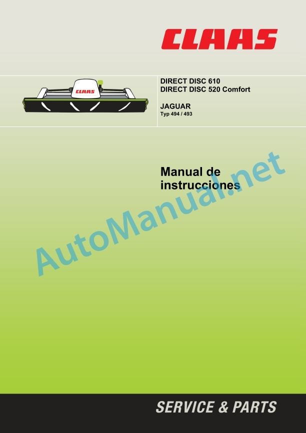
Claas Direct Disc 610 Contour C (904) Forage Harvesters Operator Manual ES
$50.00
- Model: Direct Disc 610 Contour C (904) Forage Harvesters
- Type Of Manual: Operator Manual
- Language: ES
- Format: PDF(s)
- Size: 35.4 MB
File List:
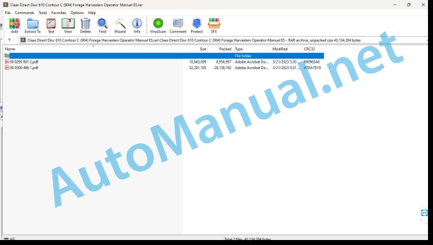
00 0295 801 2.pdf
00 0300 466 1.pdf
00 0295 801 2.pdf:
1. Introduction
Introduction
Validity
3 Prologue
Pay special attention
Identification plate
Road transport
Road driving safety device
4 Security measures
Proper use of the machine
Predictably foolish misuse
Decommissioning and garbage disposal
Warning and danger signs
General safety and accident prevention rules
Safety stickers with graphic danger symbols
Security support
5 Technical data
DIRECT DISC 610
DIRECT DISC 520 Comfort
6 Assembly
Unload/load head
Assembling the head for the first time
Assemble the skates
Attach/remove parking legs
Use the head
Adaptations in the head
Head operation on JAGUAR model 493
Head operation on JAGUAR model 494
Adaptations to the forage chopper
Additional weights
JAGUAR model 493
Reinforced drive of the power unit
JAGUAR Model 493 Mounting Kit Supply Set (D03/0090)
Mounting the 3-groove belt drive
Additional cushioning
Adjust descent speed (JAGUAR model 493 only)
JAGUAR model 494
Reinforced drive of the power unit
JAGUAR Model 494 Mounting Kit Supply Set (D03/0090)
CEBIS adjustments
Head menu
7 Before start-up
Check and observe before commissioning
Assemble the head
To assemble the head proceed as follows:
Open interlock
Lubricate the coupling flange
Attach the head
Close interlock
Connect the hydraulic system
Connect the electrical installation
Check the fit of the coupling flange to the quick coupler
Adjust the paddle rollers
Hydraulic regulation of blade rollers (supplementary equipment)
Adjust the skates
Adjust the inclination of the cutter bar
Necessary parts
Adjust the cutting bar more inclined
Adjust the cutter bar less inclined
Adjust the protection bars
Working and transport position
Transport position
Work position
Remove/park the head
8 Management
Application
Prerequisite
Multifunctional handle
Raise/lower head
Place the head
Mowing Warnings
Difficult application conditions
Adjust cutting height
Unlock/lock the pendulum chassis
Adjust the length of the chop
Chop cutting length zone
Supplementary equipment
Hydraulic regulation of blade rollers (R03/0100)
Laserpilot (R03/0090, DIRECT DISC 520 Comfort only)
Conveyor caps (D03/0080)
Additional cushioning (R05/0060, JAGUAR model 493 only)
3-groove belt drive (D03/0090)
RPM sensor
9 Maintenance
Important maintenance instructions
Hydraulic installation
Lubrication
Safety devices
Feed worm gear (A)
Bevel gear – mowing drive / drive power units (B)
Bevel Gear – Mowing Drive (C)
Bevel Gear – Mowing Drive (D)
Purge valve
cutter bar
Oil level control
Oil change
Oil capacity:
Clutches
Clutches (E, G)
Regulation of rotation torque
Mowing drive friction clutch (E)
Locking system coupling (G) of the power units
Freewheel (F) of the mowing drive
Bleed the friction clutch
Grease the drive chain
Tensioning steel roller chains
Tension the drive chain
Tension the drive chain with tensioner
Tension the drive chain with chain tensioner
Tension the V-belt
Check the V-belt
spring adjustment
Feeder auger spring tension
Adjust the pendulum chassis compensation springs
cardan shafts
Maintain cardan shafts
General instructions regarding cardan shafts
Remove/install the protection cone
Input gear protection housing
Mowing drive/input gear cardan shaft protection
Cardan shafts with locking screws
mounting lever
Lock the mower discs
mower blades
Mower blade box
Check mower blades
Mower blade quick change system
Check the mower blade holder (mower blade quick change system)
Changing bolted mower blades
Mower blade attachment (bolt-on version)
Mower discs
Check the mower discs
Changing the mower discs
Transport drums
Check the transport drum
Change the transport drum
Transport drum cover
Remove/install wear strips
Electrical installation
Adjust the rpm sensor
Level the toothed washer
Adjust the distance between the speed sensor and the toothed washer (DIRECT DISC 520 Comfort only)
Hydraulic schlauchleitungen
Anti-winding device
Adjust the anti-winding device
Soft top
Side covering
Upper side lining
Interlock
Adjust interlock
Adjust the locking rod
Bolted Assemblies
Union elements
Cleaning and care
Conservation during winter
Lubricants table
DIRECT DISC 520 Comfort
DIRECT DISC 610
Grease points
Incidents
10 Greasing scheme
Security measures
Lubricants
Lubrication
00 0300 466 1.pdf:
DIRECT DISC 610 (Subtype 0310)DIRECT DISC 520 (Subtype 0515)
1. Introduction
1.1 Information regarding the instruction manual
1.1.1 Validity of the manual
1.1.2 Information about this instruction manual
1.1.3 Symbols and indications
1.1.4 Optional equipment
1.1.5 Qualified specialized workshop
1.1.6 Maintenance information
1.1.7 Information regarding warranty
1.1.8 Spare parts and technical questions
1.2 Proper application of the machine
1.2.1 Proper machine application
1.2.2 Logically foreseeable inappropriate application
2 Security
2.1 Recognize warning signs
2.1.1 Danger symbols
2.1.2 Keyword
2.2 Safety instructions
2.2.1 Meaning of the instruction manual
2.2.2 Observe graphic danger symbols and alarm indications
2.2.3 Requirements for all people working with the machine
2.2.4 Children in danger
2.2.5 Danger zones
2.2.6 Stay between the machine and the head
2.2.7 Attach the header or transport trailer to the machine
2.2.8 Risk of injury due to rotating shafts
2.2.9 Construction changes
2.2.10 Optional equipment and spare parts
2.2.11 Control of the machine in operation
2.2.12 Use only after correct start-up
2.2.13 Technical status
2.2.14 Danger due to damage to the machine
2.2.15 Comply with technical limit values
2.2.16 Danger due to coasting parts
2.2.17 Keep safety devices operational
2.2.18 Personal protective equipment
2.2.19 Wear appropriate clothing
2.2.20 Remove dirt and loose objects
2.2.21 Prepare the machine for road traffic
2.2.22 Dangers when traveling on roads and in the countryside
2.2.23 Park the machine safely
2.2.24 Unsuitable consumables
2.2.25 Safe handling of consumables and auxiliary materials
2.2.26 Environmental protection and waste disposal
2.2.27 Fire hazard
2.2.28 Electrical shock from electrical equipment
2.2.29 Liquids under pressure
2.2.30 Hot surfaces
2.2.31 Work only on the stopped machine
2.2.32 Maintenance work and repair work
2.2.33 Lifted machine parts and loads
2.2.34 Danger from welding work
2.3 Safety signage
2.3.1 Structure of graphic hazard symbols
2.3.2 Position of warning symbols on the machine
3 Machine Description
3.1 Summary and operation
3.1.1 Machine overview
3.1.2 Gear overview
3.1.3 Summary of the direction of rotation of the mower discs
3.1.4 Machine operating mode
3.2 Optional equipment
3.2.1 Hydraulic adjustment of the paddle roller*
3.2.2 Conveyor caps*
3.2.3 High cut skates*
3.2.4 Wear pads*
3.2.5 Shims*
3.2.6 Support legs*
3.3 Identification plates and identification numbers
3.3.1 Machine identification plate
3.4 Machine information
3.4.1 Adhesive on the machine
4 Control and display instruments
4.1 Mounting frame
4.1.1 Interlocking mechanism
5 Technical data
5.1 DIRECT DISC 610
5.1.1 Suitable machines
5.1.2 Dimensions
5.1.3 Weight
5.1.4 Version
5.1.5 Lubricants
5.2 DIRECT DISC 520
5.2.1 Suitable machines
5.2.2 Dimensions
5.2.3 Weight
5.2.4 Version
5.2.5 Lubricants
6 Preparation of the machine
6.1 Turn off the machine and secure it
6.1.1 Turn off the machine and secure it
6.1.2 Secure the raised head
6.2 Access jobs and maintenance positions
6.2.1 Open and close the covers for maintenance
Open the left and right maintenance covers
Close the left and right maintenance covers
Open the cover for central maintenance
Close the lid for central maintenance
6.2.2 Open and close the hood
Open the hood
Close the hood
6.3 Adapt the chopper
6.3.1 Assemble the cutter bar starter clutch hydraulic connection*
6.3.2 Adjust the head in CEBIS
6.4 Assemble the head
6.4.1 Supply package overview
6.4.2 Assemble the sliding pads
6.5 Assemble the head
6.5.1 Open the latch
6.5.2 Grease the coupling flange
6.5.3 Attach the head
6.5.4 Close the interlocking mechanism.
6.5.5 Assemble the head with support legs.
6.5.6 Assemble the head with support legs*.
6.5.7 Connect the hydraulic hoses
6.5.8 Connect the power supply
6.5.9 Unlatching the oscillating frame
6.6 Adapt the head
6.6.1 Adjust the locking mechanism
6.6.2 Adjust the locking linkage
6.6.3 Check the claw coupling
6.6.4 Adjust dog clutch
6.7 Disassemble the head
6.7.1 Disassemble the head with support legs
6.7.2 Disassemble the head with support legs*
6.7.3 Latching the swing frame
6.7.4 Unplug the power supply
6.7.5 Uncouple the hydraulic pipes
6.7.6 Open the locking mechanism
6.7.7 Unhook the head
6.8 Prepare for road traffic
6.8.1 Placing the header on the transport trailer
6.9 Prepare for use at work
6.9.1 Raise the head of the transport trailer
6.10 Load the head
6.10.1 Raise the head
7 Management
7.1 Driving on the road
7.1.1 Driving on public roads
7.2 Settings for use at work
7.2.1 Adjust cutting height
7.2.2 Adjust the inclination of the cutter bar
Necessary parts
Remove the wear pads
Remove the sliding pad
Remove the left cutter bar
Remove the right cutter bar
Adjust the cutter bar steeper
Set the cutter bar less steep
Chock mounting position
Install the cutter bar
Assemble the sliding skids
Install wear skids
Adjust the protection bars
7.2.3 Adjusting the paddle roller
7.2.4 Adjust elevation limitation
7.2.5 Adjust the cutting length
7.3 Use at work
7.3.1 Use the head
7.3.2 Connect the head
7.3.3 Raise and lower the head
7.3.4 Switching cutting height control on and off
7.3.5 Raising and lowering the paddle roller
7.3.6 Reverse the direction of travel of the head
7.3.7 Disconnect the head
7.3.8 Take into account during the field trip
7.3.9 Mowing technique
7.3.10 Instructions on mowing
7.3.11 Difficult harvest conditions
7.3.12 Recommendation regarding environmental protection
8 Incident and solution
8.1 Summary of incidents
8.1.1 Summary of incidents on the machine
8.2 Electrical and electronic system
8.2.1 Adjust the speed sensor
9 Maintenance
9.1 Summary of maintenance intervals
9.1.1 Before starting the harvest
9.1.2 After the first 50 hours of service
9.1.3 Every 8 hours of service
9.1.4 Every 50 hours of service
9.1.5 Every 250 hours of service
9.1.6 Every 500 hours of service or annually
9.1.7 After harvest
9.2 Gearbox
9.2.1 Check the tightness of the gear
9.2.2 Check the main gear oil level
9.2.3 Change main gear oil
9.2.4 Check the timing gear oil level
9.2.5 Change the timing gear oil
9.2.6 Check the bevel gear oil level
9.2.7 Change bevel gear oil
9.2.8 Check the spur gear oil level
9.2.9 Change spur gear oil
9.3 Clutch
9.3.1 Check the overload clutch
9.3.2 Check the friction clutch
9.3.3 Ventilate the friction clutch
9.4 Cardan shaft
9.4.1 Maintenance of cardan shafts
Summary of cardan shafts
Remove/install the protection cone
9.5 Drives
9.5.1 Check the drive chain
9.5.2 Check the blade roller drive chain
9.5.3 Check the tension of the feed auger spring
9.6 Hydraulic installation
9.6.1 Check the hydraulic hoses
9.7 Mowing device
9.7.1 Check the cutter bar oil level
Check the oil level of the left cutter bar
Check the oil level of the right cutter bar
9.7.2 Change the cutter bar oil
Drain the oil from the left cutter bar
Fill the oil in the left cutter bar
Drain the oil from the right cutter bar
Fill the oil in the right cutter bar
9.7.3 Check the cutter bar oil level
Check the oil levels of the cutter bars
9.7.4 Change the cutter bar oil
Drain oil from the cutter bars
Fill the oil in the cutter bars
9.7.5 Check the mower blades
9.7.6 Replacing the mower blades
9.7.7 Check the mower discs
9.7.8 Check the blade holder
9.7.9 Change the mower discs
9.7.10 Check the conveyor drums
9.7.11 Replace the conveyor drums
9.7.12 Adjusting the winding protection
9.8 Assembly and body parts
9.8.1 Clean the machine
9.8.2 Maintain the machine
9.8.3 Check the fixing material
9.9 Greasing scheme
9.9.1 Grease the lubrication points every 50 hours of service
9.9.2 Grease the lubrication points every 250 hours of service
10 Decommissioning and waste disposal
10.1 General information
10.1.1 Decommissioning and waste disposal
11 EC declaration of conformity
11.1 DIRECT DISC 610
11.1.1 EC declaration of conformity
11.2 DIRECT DISC 520
11.2.1 EC declaration of conformity
12 Technical dictionary and abbreviations
12.1 Terms and explanations
12.1.1 Technical vocabulary
12.1.2 Abbreviations
John Deere Repair Technical Manual PDF
John Deere Repair Technical Manual PDF
John Deere Transmission Control Unit Component Technical Manual CTM157 15JUL05
John Deere Repair Technical Manual PDF
John Deere Repair Technical Manual PDF
John Deere Application List Component Technical Manual CTM106819 24AUG20
John Deere Repair Technical Manual PDF
John Deere 16, 18, 20 and 24HP Onan Engines Component Technical Manual CTM2 (19APR90)
John Deere Repair Technical Manual PDF
John Deere Repair Technical Manual PDF
John Deere Repair Technical Manual PDF
John Deere Repair Technical Manual PDF


