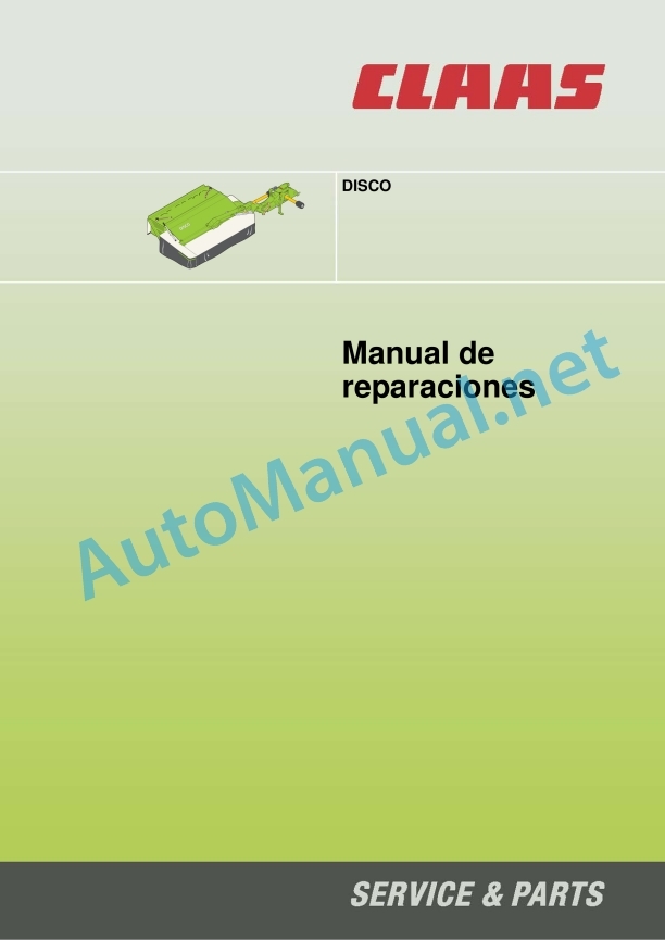
Claas Disco 3100 F Profil (623) Mower Repair Manual ES
$300.00
- Model: Disco 3100 F Profil (623) Mower
- Type Of Manual: Repair Manual
- Language: ES
- Format: PDF(s)
- Size: 8.1 MB
File List:
00 0296 639 0.pdf
00 0296 639 0.pdf:
Introduction
General data
Manual validity
Manual handling
Texts and figures
Breakdown with construction group structure
Search and find
Direction signs
Abbreviations
General repair instructions
Technical data
Advice on cost-effective repairs
Self-locking screws
Liquid screw insurance
Steel roller chains
connecting link
Tapered ring joints
Disassembly
Mounting
Head key joints
Disassembly
Mounting
Bearings with tension ring
Disassembly
Mounting
Bearings with tensioner sleeve
Disassembly
Mounting
Tension bushing
Disassembly
Mounting
Threadings with adjustment ring
Screw in
Non-tight joint with adjusting ring
Screw connections with sealing cone
Hydraulic hoses
Laying the hoses
Replacement parts
Tightening torques
Tightening torques for normal metric threads
Tightening torques for metric fine threads
Tightening torques for hydraulic unions with adjusting ring DIN 3861
Tightening torques for hydraulic unions and climatic unions with sealing cone and O-ring DIN 3865
Tightening torques for SDS hydraulic threaded fittings
Tightening torques for SDE hydraulic threaded fittings with adjustable direction
Tightening torques for oscillating hydraulic threadings
Tightening torques for hollow screws DIN 7643
Tightening torques for brake pipe threading
Tightening torques for helical thread clamps
Tightening torques for spring-loaded helical thread clamps
Tire tightening torques
Security
General data
To especially take into account
Signaling of warning and alarm indications
General protection and safety rules at work
First aid
Risk of injury from hydraulic fluid
Leave the machine
Put the machine out of service
Raise the machine on supports
Adjustment and maintenance work
Welding work
02 Gears / clutch / cardan shaft
0230 Mechanical gear
main gear
Main gear 00 0937 218 2
Preparation for work
Disassemble
Disassemble the gear
Drain oil
Remove the hub from the housing
Remove the hub axle from the housing
Disassemble the step shaft
Assemble the gear
Install the step shaft
Pre-assemble the housing hub
Adjust the teeth
Install the housing hub
Fill oil
Main gear 00 0480 604 1
Axle repair kit
Preparation for work
Disassemble
Disassemble the gear
Drain oil
Remove the hub from the housing
Remove the bevel pinion shaft
Disassemble the step shaft
Assemble the gear
Pre-assemble the pitch shaft
Assemble the step shaft
Preassemble the bevel pinion shaft
Adjust the teeth
Assemble the housing hub and housing flange
Fill oil
Main gear 00 0481 978 3 / 00 1321 234 1
Axle repair kit
Preparation for work
Disassemble
Disassembly 00 0481 978 3
Disassembly 00 1321 234 1
Disassemble the gear
Drain oil
Remove the radial shaft seal rings
Remove the hub from the housing, inlet
Remove the bevel pinion shaft
Remove the hub from the housing, outlet
Disassemble the axle
Disassemble the step shaft
Assemble the gear
Pre-assemble the pitch shaft
Install the step shaft
Pre-assemble the shaft, output
Preassemble shaft, input
Adjust the teeth
Screw on the housing flange and housing hubs
Fill oil
Assembly 00 0481 978 3
Assembly 00 1321 234 1
bevel gear
Bevel gear 00 0481 204 2
Work preparation
Disassemble the gear
Drain oil
Remove the shaft seal ring
Remove the shaft, input
Remove the bevel pinion shaft
Assemble the gear
Install the bevel pinion shaft
Install the shaft, input
Adjust the teeth
Close the casing
Fill oil
Bevel gear 00 0925 309 0
Work preparation
Disassemble the gear
Drain oil
Remove the shaft seal ring
Remove the shaft, input
Remove the bevel pinion shaft
Assemble the gear
Install the bevel pinion shaft
Install the shaft, input
Adjust the teeth
Close the casing
Fill oil
Bevel gear 00 0481 231 1
Work preparation
Disassemble
Disassemble the gear
Drain oil
Remove the radial shaft seal rings
Remove the shaft, input
Dismantle the shaft, output
Assemble the gear
Install the shaft, output
Preassemble shaft, input
Adjust the teeth
Install the shaft, input
Assemble the assembly parts
Fill oil
Bevel gear 00 0934 534 1
Work preparation
Disassemble the gear
Drain oil
Remove the shaft, input
Dismantle the shaft, output
Disassemble the step shaft
Assemble the gear
Install the step shaft
Install the shaft, output
Install the shaft, input
Adjust the teeth
close the gear
Fill oil
09 Hydraulic
0930 Cylinder
Hydraulic cylinders
Hydraulic cylinder 00 0481 044 1
Hydraulic cylinder 00 0481 072 2
Hydraulic cylinders 00 1320 912 0
Install discharge cylinder
Install discharge cylinder
Hydraulic cylinder 00 0482 340 2
Hydraulic cylinder 00 0482 341 1
Hydraulic cylinder 00 0483 638 1
Hydraulic cylinder 00 0483 660 1
Hydraulic cylinders 00 1320 405 0
Hydraulic cylinders 00 1320 911 0
23 Mowing device
2305 Cutter bar
General information of the cutter bar
Standard cutter bar
Cutter bar summary
Work preparation
auxiliary tool
Disarmament information
Drain oil
Remove the cover
Dismantle the conveyor cylinders
Remove the mower discs
Remove the skates
Remove the intermediate sprocket
Disassemble the ball bearing
Install the grooved bearing
Disassemble the rotor
Disassemble the rotor inlet
Assembly information
Preassemble the rotor
Pre-assemble the rotor inlet
Install the intermediate sprocket
Install the bushing
Screw in the casing screws
Assemble the rotor
Airtightness control
Screw the skate
Install the mower disc
Assemble the conveyor cylinder
Assemble the conveyor cylinder inlet
Assemble the cover
Fill oil
P-Cut Cutter Bar
Cutter bar summary
Work preparation
Disarmament information
Drain oil
Disassemble the conveyor cylinder
Remove the cover
Remove the mower disc
Remove the skid
Remove the intermediate sprocket
Replace the ball bearing
Disassemble the rotor
Assembly information
Preassemble the rotor
Install the intermediate sprocket
Install the bushing
Install the housing screws
Assemble the rotor
Airtightness control
Ride the skate
Install the mower disc
Adjust the mower discs
Angle control
Measure the distance of the outer mower blades
Measure the distance of the inner mower blades
Angle error control
Prepare angle correction
Remove the mower disc
Disassemble the rotor
Fix angle error
Check angle correction
Mark the position of the rotor
Assemble the rotor
Install the mower disc
Assemble the cover
Fill oil
John Deere Repair Technical Manual PDF
John Deere DF Series 150 and 250 Transmissions (ANALOG) Component Technical Manual CTM147 05JUN98
John Deere Repair Technical Manual PDF
John Deere Repair Technical Manual PDF
John Deere Parts Catalog PDF
John Deere Tractors 7500 Parts Catalog CPCQ26568 30 Jan 02 Portuguese
John Deere Repair Technical Manual PDF
John Deere Repair Technical Manual PDF
John Deere Application List Component Technical Manual CTM106819 24AUG20
John Deere Repair Technical Manual PDF
John Deere Repair Technical Manual PDF
John Deere POWERTECH E 4.5 and 6.8 L Diesel Engines TECHNICAL MANUAL 25JAN08
John Deere Repair Technical Manual PDF


