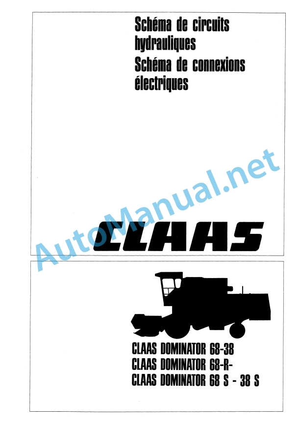
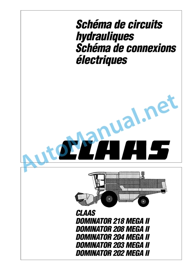
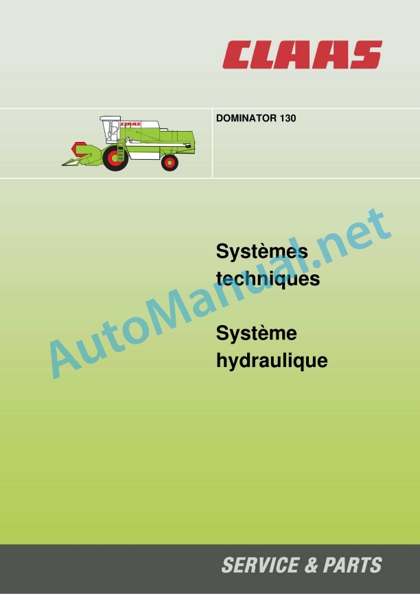
Claas Dominator 130 68 S (156) Combines Technical System FR
$300.00
- Model: Dominator 130 68 S (156) Combines
- Type Of Manual: Technical System
- Language: FR
- Format: PDF(s)
- Size: 25.2 MB
File List:
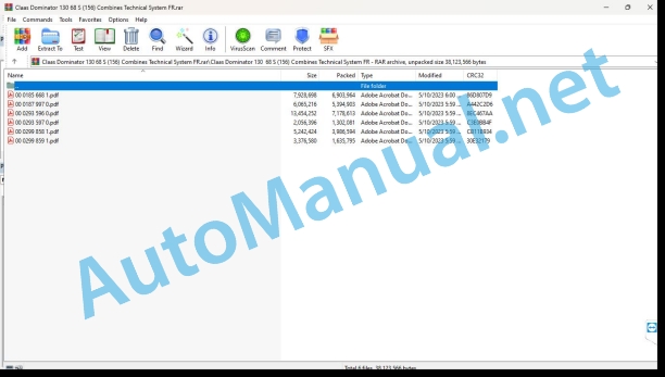
00 0185 668 1.pdf
00 0187 997 0.pdf
00 0293 596 0.pdf
00 0293 597 0.pdf
00 0299 858 1.pdf
00 0299 859 1.pdf
00 0187 997 0.pdf:
187997’0-HE-D0218-202MegaII-F-A3.pdf
00 0293 596 0.pdf:
– 1 – A4
– 3 – A4
– 5 – A4
– 6 – A4
– 7 – A4
– 8 – A4
– 9 – A4
– 10 – A4
– 11 – A4
– 12 – A4
– 13 – A4
– 14 – A4
– 17 – A4
– 18 – A4
– 21 – A4
– 22 – A4
– 23 – A4
– 24 – A4
– 27 – A4
– 28 – A4
– 31 – A4
– 32 – A4
– 33 – A4
– 34 – A4
– 35 – A4
– 36 – A4
– 37 – A4
– 38 – A4
– 39 – A4
– 40 – A4
– 41 – A4
– 42 – A4
– 43 – A4
– 44 – A4
– 45 – A4
– 47 – A4
– 48 – A4
– 51 – A4
– 52 – A4
– 53 – A4
– 54 – A4
– 55 – A4
– 56 – A4
– 57 – A4
– 58 – A4
– 59 – A4
– 60 – A4
– 61 – A4
– 62 – A4
– 63 – A4
– 64 – A4
– 65 – A4
– 66 – A4
– 67 – A4
– 68 – A4
– 69 – A4
– 70 – A4
– 71 – A4
– 72 – A4
– 73 – A4
– 74 – A4
– 75 – A4
– 76 – A4
– 77 – A4
– 78 – A4
– 79 – A4
– 80 – A4
– 81 – A4
– 83 – A4
– 84 – A4
– 85 – A4
– 86 – A4
– 87 – A4
– 88 – A4
– 89 – A4
– 90 – A4
– 91 – A4
– 95 – A4
– 96 – A4
– 97 – A4
– 98 – A4
– 99 – A4
– 100 – A4
00 0293 597 0.pdf:
DOMINATOR 130 electrical system
Construction of electrical plans
Power plant
Module pinouts
Module A12-1 – regime security (DZW)
Module A12-2 – regime security (DZW)
Module A12-3 – regime security (DZW)
Module A15 – CATERPILLAR (CAT) electronic engine control
01a – 40a
01a Main voltage supply, diesel engine starter
02a Starting the diesel engine and controlling the engine
03a Diesel engine safety
12a Flow control
13a Reverse gear warning buzzer
17a Front tool and reversing drive
25a Safety of the rotation regime
26a Machine safety
28a AUTOPILOT – (connection possibility)
30a Rotating beacon – (connection possible)
31a Flashing, hazard lights
32a Main lighting control, positioning light
34a Working lighting, instrument lighting
35a Brake lights
37a Windshield wiper
38a Air conditioning
40a Auxiliary sockets (connection possibility)
Coordination diagram
Keyword index
0293 597.0
00 0299 858 1.pdf:
Technical systems – Hydraulic system DOMINATOR 48 – 68, DO 48 from no. 15403117, DO 68 from no. 15608462
1 General hydraulics
1.1 General hydraulics
Hydraulic pumps
Oil pressure
Oil specification
Oil drain
Filling quantity
Oil filter head
Oil filter
1.2 General hydraulic controls plan
1.2.1 Plan of hydraulic controls without straw collector
Pressure measurement
1.2.2 Plan of general hydraulic controls a
Pressure measurement
2 Steering hydraulics / 3-D box control
2.1 Plan of hydraulic steering controls without AUTOPILOT
2.2 Plan of hydraulic steering controls with AUTOPILOT
2.3 Steering systelve block
2.4 Function of neutral steering
Steering control
2.5 Management check
2.6 AUTOPILOT solenoid valve
2.7 Checking the AUTOPILOT system
2.8 Control of the 3-D box
3 Operating hydraulics
3.1 Plan of hydraulic operatinntrols
3.2 Pressure limiter
3.2.1 Pressure relief valve (703) with hydraulic swivel of the drain chute
3.2.2 Pressure limiter without hydraulic swivel
3.3 Pivoting the hopper discharge chute
4/3 distributor
Hydraulic cylinder
3.4 Stop block
3.5 Flow distributor (optional) with horizontal adjustment of the reel or straw collector
3.6 Cutting height automation (optional)
3/3 distributor
3.7 Horizontal adjustment of the reel
4/3 distributor
Hydraulic cylinder
3.8 Raising/lowering the front tool, variator
Multifunction dispenser 6/9
Hydraulic cylinder for vertical adjustment of the flap
Hydraulic cylinder of speed variator
Rotating passage and restrictor with non-return valve
3.9 Foot valve of the m speed variator
3.10 Straw collector
3/3 distributor
Component Locations
Coordination diagram
0299 858.1
00 0299 859 1.pdf:
Technical systems – Electrical system DOMINATOR 48 – 68, DO 48 from no. 15403117, DO 68 fro. 15608462
Power plant
Module pinouts
Module A12-1 – regime security (DZW)
Module A12-2 – regime security (DZW)
Module A12-3 – regime safety (DZW)
Module A15 – CATERPILLAR electronic engine control (CAT)
01a Main voltage supply, diesel engine starter – with mechanical engine adjustment
01b Main voltage supply, diesel engine starter – with electronic engine control (CAT)
02a Diesel engine start and engine control – with mechanical engine adjustment
02b Diesel engine starting and engine control – with electronic engine control (CAT)
03a Diesel engine safety – with mechanical engine adjustment
03b Diesel engine safety – with electronic engine control (CAT)
12a Flow control
13a Straw collector with mechanical motor adjustment
13b Reverse/straw collector buzzer wilectronic engine adjustment (CAT)
17a Front tool and reversing drive
25a Safety of the rotation regime
26a Machine safety
28a AUTOPILOT – (connection possibility)
30a Rotating beacon – (connection possible)
31a Flashing, hazard lights
32a Main lighting control, positioning light
34a Working lighting, instrument lighting
35a Brake lights
37a Windshield wiper
38a Air conditioning – with mechanical engine adjustment
38b Air conditioning with electronic engine control (CAT)
40a Auxiliary sockets (connection possibility)
Coordination diagram
0299 859.1
John Deere Parts Catalog PDF
John Deere Tractors 6300, 6500, and 6600 Parts Catalog CQ26564 (29SET05) Portuguese
John Deere Repair Technical Manual PDF
John Deere Repair Technical Manual PDF
John Deere Application List Component Technical Manual CTM106819 24AUG20
John Deere Repair Technical Manual PDF
John Deere Repair Technical Manual PDF
John Deere Repair Technical Manual PDF
John Deere Parts Catalog PDF
John Deere Tractors 7500 Parts Catalog CPCQ26568 30 Jan 02 Portuguese
John Deere Repair Technical Manual PDF
John Deere DF Series 150 and 250 Transmissions (ANALOG) Component Technical Manual CTM147 05JUN98
John Deere Repair Technical Manual PDF
John Deere Diesel Engines POWERTECH 2.9 L Component Technical Manual CTM126 Spanish

