Claas Jaguar 900-830 (493) Forage Harvesters Technical System EN
$300.00
- Model: Jaguar 900-830 (493) Forage Harvesters
- Type Of Manual: Technical System
- Language: EN
- Format: PDF(s)
- Size: 46.6 MB
File List:
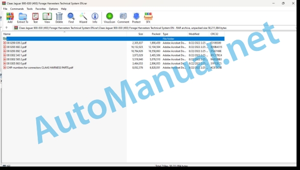
00 0290 039 2.pdf
00 0293 682 2.pdf
00 0293 892 1.pdf
00 0302 343 1.pdf
00 0302 565 2.pdf
00 0305 863 0.pdf
CHP-numbers for connectors CLAAS HARNESS PARTS.pdf
00 0290 039 2.pdf:
JAGUAR 900 – 810
Table of contents
CCN explanation
CCN (CLAAS Component Number)
Electric systems standard
Overview
Hydraulic system standard
Overview
CCN (CLAAS Component Number)
Introduction
Validity of manual
75 Central lubrication system
7505 Reservoir / Pump
Central lubrication system PCB circuit – Jaguar type 491 / 492 / 493
Measured values table
Description of function
7515 Lubrication system / Lines
Central lubrication system connection diagram
92 Diagnosis
Fault codes
Completed CIS error code table (type 492, 493, 495)
00 0293 682 2.pdf:
Contents
1 Introduction
Structure of electrical documentation
Circuit diagram
Grid co-ordinates
Interconnection list
CLAAS standard:
2 Central terminal compartment
Overview
Top view
Bottom view
Electronic components
3 Modules
Module representation
Overview 1
Overview 2
Module representation
Module A6 – Automatic air conditioner
Cab fan speed controller module A7
Module A9 – Autopilot
Module A10 – Fieldwork computer (CAB)
Module A11 – Contour
Module A14 – Intake controller
Module A15 – Electronic engine control DC
Module A17 – Engine adaptation (ADM)
Module A24 – Sharpening / Shear bar adjustment (GGS)
Module A30 – CIS terminal
Module A49 – Ground drive module
Module A53 – Adaptation (FEM) ISO bus
Module A54 – Yield meter (FEM)
Module A73 – Discharge / additive control module
Module A76 – Metal detector
4 Circuit diagrams
01a Main power supply, Diesel engine electric starting motor, Reversing horn
Circuit diagram (DIN A3)
Key to diagram
Measuring value table
Discription of function
Connector pin assignment
Interconnection list
02a Starting the diesel engine, diesel engine speed adjustment
Circuit diagram (DIN A3)
Key to diagram
Measuring value table
Discription of function
Connector pin assignment
Interconnection list
03a Diesel engine cut-off system
Circuit diagram (DIN A3) up to serial no. 49300020 diesel engine with exhaust gas standard TIER 2
Key to diagram
Measuring value table
Discription of function
Connector pin assignment
Interconnection list
03b Diesel engine monitoring
Circuit diagram (DIN A3) from serial no. 49300021 diesel engine with exhaust gas standard TIER 3
Key to diagram
Measuring value table
Discription of function
Connector pin assignment
Interconnection list
04a Road travel circuit, circulation lock valve
Circuit diagram (DIN A3)
Key to diagram
Measuring value table
Discription of function
Connector pin assignment
Interconnection list
05a Terminal, keyboard
Circuit diagram (DIN A3)
Key to diagram
Discription of function
Connector pin assignment
Interconnection list
06a CAN bus
Circuit diagram (DIN A3)
Key to diagram
Measuring value table
CAN bus network
Measured value table 50 kB CAN BUS vehicle (CLAAS CAN BUS)
Measured value table J1939 CAN bus
Measured value table ISO 11783 CAN bus
Description of function
Connector pin assignment
Interconnection list
07a Main drive
Circuit diagram (DIN A3)
Key to diagram
Measuring value table
Discription of function
Connector pin assignment
Interconnection list
09a Sharpening device without automatic shear bar adjustment
Circuit diagram (DIN A3)
Key to diagram
Measuring value table
Discription of function
Connector pin assignment
Interconnection list
09b Sharpening device with automatic shear bar adjustment
Circuit diagram (DIN A3)
Key to diagram
Measuring value table
Discription of function
Connector pin assignment
Interconnection list
10a Automatic shear bar adjustment
Circuit diagram (DIN A3)
Key to diagram
Measuring value table
Discription of function
Connector pin assignment
Interconnection list
11a Corn cracker adjustment
Circuit diagram (DIN A3)
Key to diagram
Measuring value table
Discription of function
Connector pin assignment
Interconnection list
13a Automatic upper discharge chute rotation
Circuit diagram (DIN A3)
Key to diagram
Measuring value table
Discription of function
Connector pin assignment
Interconnection list
14a Upper discharge chute rotation, upper discharge chute raise/lower
Circuit diagram (DIN A3)
Key to diagram
Measuring value table
Discription of function
Connector pin assignment
Interconnection list
15a Discharge flap close / far
Circuit diagram (DIN A3)
Key to diagram
Measuring value table
Discription of function
Connector pin assignment
Interconnection list
17a Front attachment drive metal detector
Circuit diagram (DIN A3)
Key to diagram
Measuring value table
Discription of function
Connector pin assignment
Interconnection list
17b Front attachment drive metal detector
Circuit diagram (DIN A3)
Key to diagram
Measuring value table
Discription of function
Connector pin assignment
Interconnection list
18a Stone detector
Circuit diagram (DIN A3)
Key to diagram
Measuring value table
Discription of function
Connector pin assignment
Interconnection list
19a Reel variable speed drive
Circuit diagram (DIN A3)
Key to diagram
Measuring value table
Discription of function
Connector pin assignment
Interconnection list
20a Raise / lower front attachment, with cross levelling
Circuit diagram (DIN A3)
Key to diagram
Measuring value table
Discription of function
Connector pin assignment
Interconnection list
21a Additional control unit 1 – Raise / lower roller crop press, raise / lower reel
Circuit diagram (DIN A3)
Key to diagram
Measuring value table
Discription of function
Connector pin assignment
Interconnection list
21b Additional controller 2 – Hydraulic fore and aft reel adjustment, additional hitch controller
Circuit diagram (DIN A3)
Key to diagram
Measuring value table
Discription of function
Connector pin assignment
Interconnection list
24a Contour / Autocontour, pitching dampening
Circuit diagram (DIN A3)
Key to diagram
Measuring value table
Discription of function
Connector pin assignment
Interconnection list
25a Direct Disc / speed monitoring
Circuit diagram (DIN A3)
Key to diagram
Measuring value table
Discription of function
Connector pin assignment
Interconnection list
26a Machine monitoring
Circuit diagram (DIN A3)
Key to diagram
Measuring value table
Discription of function
Connector pin assignment
Interconnection list
27a Yield meter (FEM)
Circuit diagram (DIN A3)
Key to diagram
Measuring value table
Discription of function
Connector pin assignment
Interconnection list
28a Autopilot – Touch sensor system
Circuit diagram (DIN A3)
Key to diagram
Measuring value table
Discription of function
Connector pin assignment
Interconnection list
28b Autopilot – Laser
Circuit diagram (DIN A3)
Key to diagram
Measuring value table
Discription of function
Connector pin assignment
Interconnection list
29a All-wheel drive, Central lubrication system, Servo gearshift
Circuit diagram (DIN A3)
Key to diagram
Measuring value table
Discription of function
Connector pin assignment
Interconnection list
31a Turn signal indicator system – Europe
Circuit diagram (DIN A3)
Key to diagram
Measuring value table
Discription of function
Connector pin assignment
Interconnection list
31b Turn signal indicator system – USA
Circuit diagram (DIN A3)
Key to diagram
Measuring value table
Discription of function
Connector pin assignment
Interconnection list
32a Main lighting circuit, taillight, position light
Circuit diagram (DIN A3)
Key to diagram
Measuring value table
Discription of function
Connector pin assignment
Interconnection list
33a Low beam, high beam, warning beacons
Circuit diagram (DIN A3)
Key to diagram
Measuring value table
Discription of function
Connector pin assignment
Interconnection list
34a Worklights 1
Circuit diagram (DIN A3)
Key to diagram
Measuring value table
Discription of function
Connector pin assignment
Interconnection list
34b Worklights 2
Circuit diagram (DIN A3)
Key to diagram
Measuring value table
Discription of function
Connector pin assignment
Interconnection list
35a Signal horn, brake light
Circuit diagram (DIN A3)
Key to diagram
Measuring value table
Discription of function
Connector pin assignment
Interconnection list
36a Instrument lighting, radio, mirror adjustment
Circuit diagram (DIN A3)
Key to diagram
Discription of function
Connector pin assignment
Interconnection list
37a Windscreen wiper, Windscreen washer
Circuit diagram (DIN A3)
Key to diagram
Discription of function
Connector pin assignment
Interconnection list
38a Compressor-type air conditioner
Circuit diagram (DIN A3)
Key to diagram
Measuring value table
Discription of function
Connector pin assignment
Interconnection list
38b Automatic air conditioner
Circuit diagram (DIN A3)
Key to diagram
Measuring value table
Discription of function
Connector pin assignment
Interconnection list
39a Silaging agent system
Circuit diagram (DIN A3)
Key to diagram
Measuring value table
Discription of function
Connector pin assignment
Interconnection list
40a Additional sockets, fuse tester
Circuit diagram (DIN A3)
Key to diagram
Discription of function
Connector pin assignment
Interconnection list
42a Trailer brake system
Circuit diagram (DIN A3)
Key to diagram
Discription of function
Connector pin assignment
Interconnection list
43a Electro-hydraulic ground drive (EFA)
Circuit diagram (DIN A3)
Key to diagram
Measuring value table
Discription of function
Connector pin assignment
Interconnection list
5 Diagnosis
Self-propelled forage harvester fault list, sorted by fault number
CIS fault code table for Jaguar Type 492 and 493
6 Location of components
Overview (DIN A3)
00 0293 892 1.pdf:
1 Overall hydraulic system
Tier 2 diesel engine / without cooling circuit pump
Hydraulic circuit diagram
Key to diagram
Working hydraulics pre-pressurization relief screw valve
Tier 3 diesel engine / with cooling circuit pump
Hydraulic circuit diagram
Designations
Working hydraulics pre-pressurization relief screw valve
2 Steering hydraulics
Steering without Autopilot
Steering without Autopilot circuit diagram
Key to diagram
Steering with Autopilot
Steering with Autopilot circuit diagram
Key to diagram
Autopilot valve block
Graphics
Key to diagram
Description of function
Function diagram, neutral
Graphics
Key to diagram
Description of function
Function diagram, actuated by steering
Graphics
Key to diagram
Description of function
Testing and measurements
Description of function
Testing the steering system
Description of function
3 Working hydraulics
Hydraulic circuit diagram
Working hydraulics circuit diagram
Key to diagram
Main valve: Circulation shut-off valve, front attachment raise/lower solenoid valve
Graphics
Key to diagram
Description of function
Upper discharge chute valve combination / discharge flap with pressure accumulator
Graphics
Key to diagram
Description of function
Hitch solenoid valve
Graphics
Key to diagram
Description of function
Sharpening, additional control unit 1, additional control unit 2 solenoid valve
Graphics
Key to diagram
Description of function
Corn cracker
Graphics
Key to diagram
Adjusting and venting
Upper discharge chute rotation drive motor
Graphics
Key to diagram
Front attachment load switch-over valve
Graphics
Key to diagram
Description of function
Pressure accumulator volume switch-over valve (Direct Disc option)
Graphics
Key to diagram
Description of function
Pitching dampening
Operation
Description of function
Testing and measuring
Graphics
Measuring pre-conditions
Set values
4 Low-pressure hydraulic system
Hydraulic circuit diagram
Low-pressure hydraulic system circuit diagram
Designations
All-wheel drive, servo gearshift, cover, reverse front attachment, front attachment clutch valve block
Designations
Description of function
Main drive valve block
Designations
Description of function
Pressure relief valve
Designations
Description of function
Shifter rail locking hydraulic cylinder
Designations
Description of function
Suction arm drive flow control valve
Designations
Description of function
Suction arm drive motor
Designations
Line header
Designations
Knife support valve cylinder
Designations
Description of function
Testing and measurements
Designations
Measuring pre-condition
5 Feeder hydraulics
Hydraulic feeder drive, components
Designations
Main drive, decelerated
Circuit diagram
Designations
Description of function
Main drive ON
Circuit diagram
Designations
Description of function
Reversing
Circuit diagram
Designations
Discription of function
Feeder OFF
Circuit diagram
Designations
Discription of function
Circuit diagram
Designations
Description of function
Quick stop
Circuit diagram
Designations
Description of function
6 Ground drive hydraulics
Overall circuit diagram
Ground drive hydraulics circuit diagram
Designations
Ground drive control
Variable-displacement pump
Designations
Variable-displacement motor
Designations
Description of function
High-pressure sensor (B97, B98)
Designations
Description of function
Testing and measurements
Pressure testing with the high-pressure sensors (B97, B98), pressure display in the CIS terminal.
High-pressure sensors measured value table (B97, B98)
Functional check
7 Compressed-air system
Trailer brake system
Circuit diagram
Key to diagram
Description of function
Engine restrictor / Compressed-air coupling
Circuit diagram
Key to diagram
Description of function
8 Location of components
Overview
Individual components
Overview
00 0302 343 1.pdf:
PROFI CAM 3
Table of contents
General information
Marking of warnings and hazard prevention notes
First-aid measures
CCN explanation
CCN (CLAAS Component Number)
Electric system standard
Overview
Hydraulic system standard
Overview
CCN (CLAAS Component Number)
10 Electrical / Electronic equipment
1030 Board computer / Indicators
Camera system
Description of function
1097 Testing / Measuring / Adjusting
Testing / measuring / adjusting the PROFI CAM
Checking the fuse in the video channel select box (C102)
Testing the video camera connector (C055)
1098 Fault / remedy
Fault / remedy PROFI CAM
The video monitor (C101) shows no image or cannot be switched on (indicator light fails to light up)
Video monitor (C102) displays a blue image either permanently or temporarily
The video monitor image is blurred
Replacing the fuse in the video channel select box (C102)
Connection and connecting cable with video camera (C055)
00 0302 565 2.pdf:
Sensor system
Table of contents
CCN explanation
CCN (CLAAS Component Number)
Electric system standard
Overview
Hydraulic system standard
Overview
CCN (CLAAS Component Number)
Introduction
Safety rules
Safety and hazard information
10 Electrical / Electronic equipment
1097 Testing / Measuring / Adjusting
Test report of the angle sensor (0011780.x)
Application of test report
Required tools
Test report of the angle sensor (0011780.x)
Testing / Measuring / Adjusting of angle sensor (0011780.x)
1. Reason for test
2. Mechanical test of angle sensor
3. Electric test with CDS
4. Electric test with multimeter
5. Mechanical test of connecting cable
Completing the machine
Test report of position and speed sensors
Application of test report
Required tools
Sensor variants
Part numbers of speed sensors
Part number of position sensor
Test report of position and speed sensors
Testing / measuring / adjusting of position and speed sensors
1. Reason for test
2. Mechanical test
3. Electric test with CDS
4a. Installation dimensions
Check of installation dimension
Installation dimensions of gearbox speed sensor (0011 799.x) and cam speed sensor (0011 810.x)
Installation dimension of position sensor (0011 815.x)
4b. Installation position
Centring of sensor
Metal-free zone
5. Electric test with multimeter
Voltage measurement
Direction of rotation and speed sensor (0011 605.x)
Measured values table
6. Mechanical test of connecting cable
Completing the machine
Test report of the urea sensor (00 0773 207 x)
Application of test report
Required tools
Parts number of the urea sensor
Test report of the urea sensor
Testing / measuring / adjusting urea sensor
1. Reason for test
2. Mechanical test
3. Mechanical test of connecting cable
4. Electric test with multimeter
5. Component test with the CDS
00 0305 863 0.pdf:
LEXIONJAGUARXERION
Table of contents
Introduction
Notes on the manual
Validity of manual
Information about this Technical Systems Manual
Identifying warnings
Hazard signs
Signal word
01 Engine
0125 Injection / Fuel system
Injection / fuel system
Required tools and aids
Line valves for connecting to the engine
Valves and adapters for tank feed and return lines
Measuring setup (possible variant)
Test procedure
A – Leakage test of tank return line and possibly of tank suction line
B – Leakage test of feed lines (possibly including fuel sediment filter)
C – Test of non-return valve in the line (if provided)
D – Leakage test of return lines (possibly including the fuel cooler)
E – Leakage test of fuel sediment filter
F – Leakage test of engine
Steps 1 – 3
Fuel diagrams
Remarks about the circuit diagrams
LEXION fuel diagram
Key to diagram
JAGUAR with Mercedes-Benz OM47x LA
Key to diagram
JAGUAR with MAN D2862 (V12)
Key to diagram
CHP-numbers for connectors CLAAS HARNESS PARTS.pdf:
CLAAS HARNESS PARTS
Table of contents
10 Electrical / Electronic equipment
1081 Overview of connectors
CLAAS HARNESS PARTS (CHP)
John Deere Repair Technical Manual PDF
John Deere Repair Technical Manual PDF
John Deere Repair Technical Manual PDF
John Deere Repair Technical Manual PDF
John Deere Diesel Engines POWERTECH 2.9 L Component Technical Manual CTM126 Spanish
John Deere Repair Technical Manual PDF
John Deere Repair Technical Manual PDF
John Deere 18-Speed PST Repair Manual Component Technical Manual CTM168 10DEC07
John Deere Repair Technical Manual PDF
John Deere Application List Component Technical Manual CTM106819 24AUG20
John Deere Parts Catalog PDF
John Deere Harvesters 8500 and 8700 Parts Catalog CPCQ24910 Spanish
John Deere Repair Technical Manual PDF

