Claas Jaguar 990-930 (502) Forage Harvesters Repair Manual FR
$300.00
- Model: Jaguar 990-930 (502) Forage Harvesters
- Type Of Manual: Repair Manual
- Language: FR
- Format: PDF(s)
- Size: 321 MB
File List:
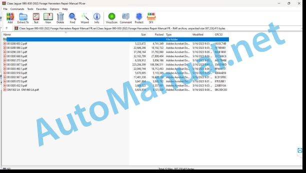
00 0288 603 2.pdf
00 0288 988 2.pdf
00 0296 339 1.pdf
00 0300 668 8.pdf
00 0302 273 3.pdf
00 0303 067 5.pdf
00 0303 463 1.pdf
00 0303 918 0.pdf
00 0303 967 1.pdf
00 0305 072 0.pdf
00 0305 432 0.pdf
OM 502 LA OM 460 LA.pdf
00 0288 603 2.pdf:
Contents
Bedknife Measuring Instructions
1 Actual state
1.1 Determine machine data
1.2 Sharpening and checking chopping knives
1.3 Check the counterblade
Illustrations of bedknife wear
1.4 Determine the stress state of the counterblade
2 Measures
2.1 Measure the drum radius
2.2 Measuring drum concentricity
Measuring position measurement result B – right side and left side (in the direction of travel)
Measuring position measurement result D – right side and left side (in the direction of travel)
2.3 Adjust the counterblade with CEBIS
2.4 Measuring the leverage difference
2.5 Measure the actual bedknife gap (once the adjustment process has been successfully completed)
2.6 Measure the shape of the drum across the width
2.7 Measure the pivoting torque of the bedknife support
3 Measured values before the measures to be taken
Measured values before the measures to be taken
4 Measures
Arrangements to take
5 Measured values after the arrangements to be made
Measured values after the arrangements to be made
00 0288 988 2.pdf:
MAN D2862-V12 Tier 4 / 5LE 133LE 134
Contents
Introduction
General instructions
Validity of the notice
Use of the instructions
Texts and illustrations
Plan with module structure
Seek and find
Steering Specifications
Abbreviations
Specialized terminology
General repair instructions
Technical characteristics
Tips for correct repair
Self-locking screws
Liquid screw brake
Steel roller chains
Quick hitch
Type E quick coupler with spring
Tler with wire
Tler with pins
Assemblies using conical ring
Disassembly
Assembly
Heel pin assemblies
Assembly
Clamp ring bearing
Disassembly
Assembly
Clamp sleeve bearing
Assembly
Clamping sleeve
Removal of version A
Submission of version B
To set down
Clamping sleeve version A
Clamping sleeve version B
Circlips
Cutting ring fittings
To screw
Leaky cutting ring fittings
Sealing Cone Fittings
Hydraulic flexible lines
Passage of hoses
Treatment of sealing surfaces
Spare parts
Tightening torques
Tightening torques for hexagonal or hexagon socket screws/nuts, head without collar or flange (man factory standard M 3059)
Tightening torques for metric ISO threads
Tightening torques for metric fine pitch threads
Tightening torques for screw connections with bicone connection and hydraulic connections with flexible sealing gasket
Tightening torques for hydraulic connections with cutting ring
Tightening torques for hydraulic screwed coupling SDS form B and E
Tightening torques for hydraulic swivel screw connections
Tightening torques for hollow screws (with copper seal)
Tightening torques for hydraulic screwed coupling SDE form H, adjustable
Tightening torques for brake line screw connections
Tightening torques for tangent screw clamps
Tightening torques for hose clamps with round bolts
CCN explanation
CCN (CLAAS Component Number – CLAAS part number)
Electrical standard
Hydraulic standard
CCN (CLAAS Component Number – CLAAS part number)
Security
Foreword
Explanation of symbols
Staffing Requirements
Instructions to avoid accidents and personal injury
Instructions to avoid damage to health and the environment
Limitation of liability for spare parts and accessories
Notes to avoid damage and premature wear to the engine
Emergency driving program on engines with electronic control device
Tips for working on common rail system
Use of AdBlue® / DEF
Engine overhaul
Assembly tips
01 Motor
0102 Complete set
Engine characteristics
Technical characteristics
Engine Description
Engine components
Technical characteristics
Technical characteristics
Technical characteristics
Lighting order
Start the engine manually
Special tool for the engine in installed position
Special tool when the engine is removed
Start the engine in the parked position
Start the engine in the stored position
0105 Engine suspension
Left side engine mount
Technical characteristics
To set down
Right side engine mount
Technical characteristics
To set down
Crane Eyelets
Technical characteristics
To set down
0110 Motor housing
Technical charateristics
Disassemble
To asseble
To set down
Crankcase air bleeding
Technical characteristics
Technical characteristics
Preparing for work
Remove the air bleeder from the left side crankcase
Install the crankcase air bleeder
Remove the air bleeder from the right side crankcase
Install the right side crankcase air bleeder
Cylinder liners
Technical characteristics
Preparing for work
Special tool
To set down
Crankcase sealing
Technical characteristics
Technical characteristics
Special tool
Remove the lip ring with spring from the rear crankshaft
Install the rear crankshaft lip ring with spring
Remove the lip ring with spring from the front crankshaft
Install the front crankshaft lip ring with spring
Front cover
Technical characteristics
Preparing for work
To set down
Flywheel housing
Technical characteristics
Technical characteristics
Disassemble
To assemble
To set down
0115 Powertrain
Technical characteristics
Special tool
Disassemble
To assemble
To set down
Measure the projection
Connecting rod
Technical characteristics
Special tool
To set down
Crankshaft
Technical characteristics
Preparing for work
Special tool
Check axial play
Check radial clearance
To set down
Oscillation damper
Technical characteristics
Special tool
Disassemble
To assemble
To set down
Flywheel
Technical characteristics
Special tool
To set down
Replace the ring gear
Steering housing drive gears
Technical characteristics
Preparing for work
Special tool
Disassemble the intermediate gear
Assemble the intermediate gear
To set down
Crankshaft speed sensor
Technical characteristics
Preparing for work
To set down
Piston cooling
Technical characteristics
Remove the oil injection nozzle
Install the oil injection nozzle
0120 Cylinder head – Valves – Distribution
Upper valve cover
Technical characteristics
Preparing for work
To set down
Cylinder head
Technical characteristics
Preparing for work
Special tool
To set down
Rocker arm
Technical characteristics
Special tool
Disassemble
To assemble
To set down
Technical characteristics
Preparing for work
Special tool
Check the valves
Check valve clearance
Adjust valve clearance
Check valve lift
Valve Springs and Valve Stem Seals
Technical characteristics
Preparing for work
Special tool
To set down
Camshaft
Technical characteristics
Special tool
To set down
Camshaft sprocket
Technical characteristics
Disassemble
To assemble
To set down
Camshaft speed sensor
Technical characteristics
Preparing for work
To set down
0125 Injection system, fuel supply
Fuel filter
Technical characteristics
Preparing for work
To set down
Fuel Service Center
Technical characteristics
Technical characteristics
Preparing for work
Special tool
Disassemble
To assemble
To set down
Fuel lines
Technical characteristics
Preparing for work
Special tool
To set down
Fuel Return Lines
Technical characteristics
Technical characteristics
Preparing for work
Special tool
Remove the left side fuel return lines
Install the left side fuel return lines
Remove the right side fuel return lines
Install the right side fuel return lines
CR rail pump pressure line
Technical characteristics
Preparing for work
Special tool
To set down
Injection pressure line
Technical characteristics
Technical characteristics
Preparing for work
Special tool
Remove the left side injection pressure lines
Install the left side injection pressure lines
Remove the right side injection pressure lines
Install the right side injection pressure lines
Technical characteristics
Technical characteristics
Preparing for work
Special tool
Remove the left side ramp
Install the left side ramp
Remove the right side ramp
Install the right side ramp
Common-Rail pressure relief valve
Technical characteristics
Preparing for work
Special tool
To set down
Injector with nozzle (Common-Rail)
Technical characteristics
Preparing for work
Special tool
To set down
High pressure pump
Technical characteristics
Technical characteristics
Technical characteristics
Preparing for work
Special tool
Remove the high pressure pump at the front
Install the high pressure pump at the front
Remove the high pressure pump at the rear
Install the high pressure pump at the rear
Disassemble the high pressure pump
Assemble the high pressure pump
High pressure pump drive housing
Technical characteristics
Technical characteristics
Preparing for work
Disassemble
To assemble
To set down
EDC Fuel Temperature Sensor
Technical characteristics
Preparing for work
Special tool
To set down
Fuel pressure sensor
Technical characteristics
Preparing for work
Special tool
To set down
Rail Pressure Sensor / Common-Rail Pressure Transmitter
Technical characteristics
Preparing for work
Special tool
To set down
0130 Lubrication system
Oil module (left side)
Technical characteristics
Disassemble
To assemble
To set down
Oil module (right side)
Technical characteristics
Disassemble
To assemble
To set down
Oil pumps
Technical characteristics
Special tool
To set down
Oil pressure sender/sensor left side
Technical characteristics
Preparing for work
To set down
Oil pressure sender/sensor right side
Technical characteristics
Preparing for work
To set down
Engine oil temperature sender
Technical characteristics
Preparing for work
To set down
0135 Cooling system
Cooling liquid
Technical characteristics
Special tool
Coolant elbow (coolant pump)
Technical characteristics
Disassemble
To assemble
To set down
Coolant line (air compressor)
Technical characteristics
To set down
Coolant elbow (right side engine block)
Technical characteristics
Disassemble
To assemble
To set down
Coolant elbow (left side engine block)
Technical characteristics
To set down
Coolant line (heating inlet)
Technical characteristics
To set down
Coolant line (left side cylinder head)
Technical characteristics
To set down
Coolant line (right side cylinder head)
Technical characteristics
To set down
Coolant elbow (thermostat housing)
Technical characteristics
To set down
Coolant thermostat
Technical characteristics
Special tool
Disassemble
To assemble
To set down
Coolant pump
Technical characteristics
To set down
Coolant temperature sender
Technical characteristics
Preparing for work
To set down
0140 Exhaust device
Exhaust gas manifold (right side)
Technical characteristics
Preparing for work
Disassemble
To assemble
To set down
Exhaust gas manifold (left side)
Technical characteristics
Preparing for work
Disassemble
To assemble
To set down
Exhaust gas turbocharger (left side)
Technical characteristics
Special tool
To set down
Exhaust gas turbocharger (right side)
Technical characteristics
Special tool
To set down
Turbocharger suction elbow
Technical characteristics
Technical characteristics
Remove the left side turbocharger suction elbow
Install the left side turbocharger suction elbow
Remove the right side turbocharger suction elbow
Install the right side turbocharger suction elbow
0145 Air suction
Charge air pipe
Technical characteristics
Disassemble
To assemble
To set down
Suction elbow (left side)
Technical characteristics
To set down
Suction elbow (right side)
Technical characteristics
Disassemble
To assemble
To set down
Intake pressure sensor/intake pressure probe
Technical characteristics
To set down
0150 Engine assembly parts
Technical characteristics
To set down
Generator
Technical characteristics
Preparing for work
Special tool
To set down
Remove the pulley
Install the pulley
Generator support
Technical characteristics
To set down
Belt tensioner for generator drive belt
Technical characteristics
Assembly tips
Air compressor
Technical characteristics
Technical characteristics
Preparing for work
Special tool
Disassemble
To assemble
To set down
Compressor closing plate
Technical characteristics
Preparing for work
To set down
0155 Engine controls
Control device console
Technical characteristics
Preparing for work
To set down
Motor control device
Technical characteristics
To set down
0165 Exhaust gas aftertreatment
Urea solution
Preparing for work
Special tool
Check the urea solution (cleanliness)
Check the urea solution (density)
Power module
Technical characteristics
Preparing for work
To set down
Modular exhaust gas aftertreatment system
Technical characteristics
Preparing for work
Assembly tips
To set down
Electronics for evaluating temperature sensors
Technical characteristics
Preparing for work
Assembly tips
Disassemble
To assemble
To set down
NOx sensor evaluation electronics
Technical characteristics
Preparing for work
Assembly tips
Disassemble
To assemble
To set down
Sealing ring of the DEF / AdBlue® / AUS32 dosing unit
Technical characteristics
To set down
DEF / AdBlue® / AUS32 dosing unit
Technical characteristics
Preparing for work
To set down
Cable duct
Technical characteristics
To set down
Plate E (CAN modules)
Technical characteristics
To set down
DEF / AdBlue® / AUS32 mixing unit
Technical characteristics
To set down
Assembly by Teconnex collar – V
Technical characterist
Disassemble
To assemble
set down
Standard support with flat band collar
Technical characteristics
To set down
SCR catalyst outlet housing
Technical characteristics
Disassemble
To assemble
To set down
Canning SCR
Technical characteristics
Disassemble
To assemble
To set down
00 0296 339 1.pdf:
Mercedes-Benz OM502LA
Contents
Introduction
General instructions
Validity of the notice
Use of the Notice
Texts and illustrations
Classification by module structure
Seek and find
Directions
Abbreviations
Specialized terms
General repair instructions
Technical specifications
Tips for correct repair
Self-locking screws
Liquid screw brake
Steel roller chains
Chain closing link
Tapered fittings
Disassembly
Assembly
Heel pin connections
Disassembly
Assembly
Clamp ring bearing
Disassembly
Assembly
Clamp sleeve bearing
Disassembly
Assembly
Clamping sleeve
Disassembly
Assembly
Circlips
Threaded fittings with cutting ring
To screw
Sealing failure of the cutting ring connection
Bicone ring screw connections
Hydraulic flexible lines
Hose routing
Treatment of sealing surfaces
Spare parts
Tightening torques
Tightening torques for metric coarse threads
Tightening torques for metric fine pitch threads
Tightening torques for hydraulic screw connections and air conditioning system screw connections with bicone ring and O-ring DIN 3865
Tightening torques for hydraulic connections with cutting ring DIN 3861
Tightening torques for SDS hydraulic screwed sleeve
Tightening torques for hydraulic swivel threaded connections
Tightening torques for hollow screws DIN 7643
Tightening torques for SDE adjustable screwed hydraulic coupling
Tightening torques for brake line screw connections
Tightening torques for tangent screw clamps
Tightening torques for spring-controlled tangent screw clamps
CCN explanation
CCN (CLAAS Component Number – CLAAS part number)
Electrical standard
Hydraulic standard
CCN (CLAAS Component Number – CLAAS part number)
Security
General instructions
Important
Marking of warnings and dangers
Instructions to avoid accidents and personal injury
Inspection, adjustment and repair work
Engine operation
Suspended loads
Work on tubular pipes and flexible pipes
Work on the electrical system
Work on the hydraulic system
Electric welding
Paint work
Works with urea solution
Notes to avoid damage and premature wear
Limits of liability
Shutdown and storage
Instructions to avoid damage to health and the environment
Preventive measures to protect against damage to health and the environment
Disposal of operating consumables, secondary consumables
Notes for working on the diesel engine
Protection against accidents
Cleanliness
Assembly tips
Engine overhaul
Commissioning after engine overhaul
First aid measures
01 Motor
0102 Complete set
Typical model
Rated motor characteristic data
Engine Description
Engine components
Lighting order
Start the engine manually
Special tool for the engine in mounted position
Special tool for the engine in disassembled position
Start the engine manually in the up position
Start the engine manually in the disassembled position
0105 Engine suspension
Fixing eyelet
Technical characteristics
0110 Motor housing
Special tool
Technical characteristics
To set down
Front crankshaft seal
Special tool
Technical characteristics
Remove the lip ring with spring
Install the lip ring with spring
Remove the cassette seal
Install the cassette seal
Rear crankshaft seal
Special tool
Technical characteristics
To set down
Crankcase cover
Special tool
Technical characteristics
To set down
Steering housing cover
Special tool
Technical characteristics
Valid for model: 942.993
To set down
Valid for model: 942.993
Steering cover
Preparing for work
Technical characteristics
To set down
Steering cover
Preparing for work
Technical characteristics
To set down
0115 Powertrain
Special tool
Technical characteristics
Disassemble
To assemble
To set down
To set down
Measure the projection
Connecting rod
Technical characteristics
To set down
Cylinder liner
Special tool
Technical characteristics
To set down
Valid for model: 458.99x
Measure the projection
Measure the cylinder bore
Crankshaft
Special tool
Technical characteristics
To set down
Crankshaft bearing ring
Special tool
Technical characteristics
To set down
Vibration damper
Special tool
Technical characteristics
To set down
Flywheel
Special tool
Technical characteristics
To set down
Replace the ring gear
Replace the bearing race
0120 Cylinder head – Valves – Distribution
Upper valve cover
Technical characteristics
Cylinder head
Special tool
Technical characteristics
Disassemble
To assemble
To set down
Rocker arm
Special tool
Technical characteristics
Assembly tips
Replace the roller pusher
Special tool
Technical characteristics
Assembly tips
Check the valves
Adjust valve clearance
Valve Springs and Valve Stem Seals
Special tool
Mercedes-Benz
Technical characteristics
To set down
Valve guide
Preparing for work
Special tool
Technical characteristics
To set down
Camshaft
Special tool
Technical characteristics
To set down
0125 Injection system, fuel supply
Fuel system
Cylinder head injection line
Special tool
Technical characteristics
Assembly tips
Cylinder head leak lines
Technical characteristics
Nozzle support combination
Special tool
Technical characteristics
To set down
Protective sleeve
Special tool
Technical characteristics
Assembly tips
Plug-in pump
Special tool
Preparing for work
Technical characteristics
To set down
Fuel pump
Preparing for work
Technical characteristics
To set down
Fuel filter housing
Technical characteristics
0130 Lubrication system
Lubricating oil system
Special tool
Oil injection nozzle
Technical characteristics
Assembly tips
Oil filter housing
Preparing for work
Technical characteristics
To set down
Oil cooler
Technical characteristics
Assembly tips
Oil pressure relief valve
Technical characteristics
Assembly tips
Oil pump
Technical characteristics
Assembly tips
0135 Cooling system
Cooling liquid
Special tool
Technical characteristics
Clean the coolant circuit
Coolant pump
Special tool
Technical characteristics
Disassemble
To assemble
To set down
Coolant thermostat
Preparing for work
Technical characteristics
To set down
0140 Exhaust device
Exhaust gas collector
Technical characteristics
To set down
Exhaust gas collector
Technical characteristics
To set down
Exhaust collector tube
Technical characteristics
Assembly tips
Exhaust gas turbocharger suction tube
Technical characteristics
Assembly tips
Exhaust gas turbocharger
Special tool
Technical characteristics
To set down
Check axial play
Check radial clearance
Exhaust gas turbocharger
Special tool
Technical characteristics
To set down
Check axial play
Check radial clearance
Catalyst
Preparing for work
Technical characteristics
Assembly tips
0145 Air suction
Suction housing
Technical characteristics
Valid for model with exhaust gas turbochargers
Valid for the model with two exhaust gas turbochargers
To set down
Valid for the model with two exhaust gas turbochargers
Valid for model with exhaust gas turbochargers
0150 Engine assembly parts
Preparing for work
Technical characteristics
To set down
Remove the magnetic switch
Install the magnetic switch
Remove the starter gear
Install the starter gear
Generator
Special tool
Technical characteristics
To set down
Remove the pulley
Install the pulley
Generator
Special tool
Technical characteristics
Generator (G002)
Generator (G002)
Generator (G003)
Generator (G003)
Generator (G003)
To set down
Generator (G002)
Generator (G002)
Generator (G003)
Generator (G003)
Generator (G003)
Remove the pulley
Install the pulley
Generator Drive Belt Tensioner
Technical characteristics
Assembly tips
Compressor
Special tool
Technical characteristics
Check oil ejection
Remove the drive wheel
Install the drive gear
Remove the cylinder head
Valid for model: 942.993
Disassemble the cylinder head
Assemble the cylinder head
Install the cylinder head
Valid for model: 942.993
Remove the piston and cylinder liner
Install the piston and cylinder liner
Remove the crankshaft and connecting rod
Install the crankshaft and connecting rod
0155 Engine controls
MR/PLD control device
Technical characteristics
Assembly tips
0165 Exhaust gas aftertreatment
Exhaust aftertreatment system
Preparing for work
Special tool
Technical characteristics
Check the urea solution (cleanliness)
Check the urea solution (density)
Urea heating valve
Preparing for work
Special tool
Technical characteristics
To set down
Urea pump
Preparing for work
Special tool
Technical characteristics
To set down
Remove the pressure accumulator
Install the pressure accumulator
Remove the pressure reducing valve
Install the pressure reducing valve
Remove the suction filter
Install the suction filter
Check the set of electrical cables
Fill the pressure accumulator
Urea Dosing Unit
Preparing for work
Special tool
Technical characteristics
Assembly tips
Urea injector
Technical characteristics
Assembly advice
0190 Accessories
Motor insulation
Preparing for work
Technical characteristics
Motor insulation
Preparing for work
Technical characteristics
To set down
00 0300 668 8.pdf:
Repair instructions
Contents
Introduction
Notes on the instructions
Validity of the notice
Repair manual information
Use of the instructions
Classification in module/group structure
Seek and find
Directions
General repair instructions
Technical characteristics
Tips for correct repair
Self-locking screws
Liquid screw brake
Steel roller chains
Quick hitch
Type E quick coupler with spring
Type G quick coupler with wire
Type S quick coupler with pins
Assemblies using conical ring
Disassembly
Assembly
Heel pin assemblies
Assembly
Clamp ring bearing
Disassembly
Assembly
Clamp sleeve bearing
Assembly
Clamping sleeve
Removing version A
Removing version B
To set down
Clamping sleeve version A
Clamping sleeve version B
Circlips
Lip rings with spring
Hose clamps
Tightening torque
Tightening torques
Collar Alignment
Auxiliary mounting means
Assembly tools
Cutting ring fittings
To screw
Leaky cutting ring fittings
Sealing Cone Fittings
Hydraulic flexible lines
Passage of hoses
Diaphragm accumulator (pressure accumulator) according to factory standard CLAAS CN 24 0403
Features
Means of exploitation
Service and assembly
Modification of gas filling
Special tool
Treatment of sealing surfaces
Spare parts
Operating consumables
Welding work
ESD protective measures
Special tool
ESD protective measures
Inspection and repair advice
Tightening torques
Screw types according to CLAAS factory standard CN 02 5000
Description of the screw type
Tolerance class
Tightening instruction
Tightening torques for metric ISO thread
Tightening torques for metric precision threads
Tightening torques for hydraulic screw connections with cutting ring
Tightening torques for pipe fittings with conical sealing fitting and hydraulic fittings with soft sealing gasket
Tightening torques for nuts for feed-through fitting, straight and angular
Tightening torques for hydraulic screwed coupling SDS form B and E
Tightening torques for hydraulic screwed socket SDS form F and sealing screw
Tightening torques for hydraulic screwed coupling SDS form H
Tightening torques for form E cover screws
Tightening torques for hydraulic screwed coupling form C, conical thread
Tightening torques for hydraulic screwed coupling SDE form F, adjustable
Tightening torques for hydrau
John Deere Repair Technical Manual PDF
John Deere Repair Technical Manual PDF
New Holland Service Manual PDF
John Deere Repair Technical Manual PDF
John Deere Repair Technical Manual PDF
John Deere Diesel Engines PowerTech 4.5L and 6.8L – Motor Base Technical Manual 07MAY08 Portuguese
John Deere Repair Technical Manual PDF
John Deere Repair Technical Manual PDF
John Deere Parts Catalog PDF
John Deere Tractors 7500 Parts Catalog CPCQ26568 30 Jan 02 Portuguese
John Deere Parts Catalog PDF
John Deere Harvesters 8500 and 8700 Parts Catalog CPCQ24910 Spanish

