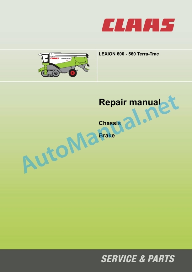
Claas Lexion 570 580 R (585) Combines Repair Manual EN
$300.00
- Model: Lexion 570 580 R (585) Combines
- Type Of Manual: Repair Manual
- Language: EN
- Format: PDF(s)
- Size: 191 MB
File List:
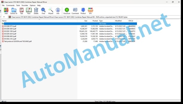
00 0288 975 0.pdf
00 0290 380 0.pdf
00 0293 109 0.pdf
00 0295 424 0.pdf
00 0296 400 0.pdf
00 0302 218 2.pdf
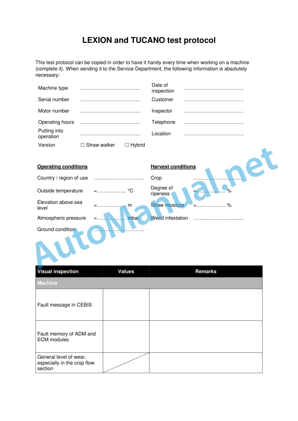
Test protocol LEXION and TUCANO.pdf
00 0288 975 0.pdf:
LEXION 770-405
Table of contents
Introduction
General information
Validity of manual
Using the manual
Text and figures
Document structure based on sub-assemblies
Search and find
Directions
Abbreviations
Technical terms
General information
Important
Hazard signs
Signal word
General safety and accident prevention regulations
Combine-harvester safety and accident prevention regulations
First aid measures
Leaving the machine
Battery isolating switch
Putting the machine out of operation
02 Gearbox / Clutch / Universal drive shaft
0210 Oscillation damper
Oscillation damper
Technical specifications
Work preparation
Installation
Oscillation damper
Technical specifications
Work preparation
Installation
Oscillation damper
Technical specifications
Work preparation
Installation
00 0290 380 0.pdf:
Contents
1 Introduction
1.1 General information
1.1.1 Validity of manual
2 Feed rake conveyor
2.1 Feed rake conveyor
2.1.1 Replacing the HP feed rake conveyor anti-slip strips
3 Straw discharge
3.1 Chaff spreader
3.1.1 Overview of chaff spreader / chaff spreader fan LEXION 600 – 560 (type 589 – 584)
3.1.2 Overview of radial spreader LEXION 600 – 560 (type 589 – 584)
3.2 Straw spreader
3.2.1 Overview of straw spreader
4 Drives
4.1 Drive belts / drive chains
4.1.1 Drive diagram, left side (LEXION 600 with JET STREAM cleaning system)
4.1.2 Drive diagram, right side (LEXION 600 with JET STREAM cleaning system)
4.1.3 Drive diagram, left side (LEXION 580 with standard cleaning system)
4.1.4 Drive diagram, right side (LEXION 580 with standard cleaning system)
4.1.5 Drive diagram, left side (LEXION 570 with standard cleaning system)
4.1.6 Drive diagram, right side (LEXION 570 with standard cleaning system)
4.1.7 Drive diagram, left side (LEXION 570 with JET STREAM cleaning system)
4.1.8 Drive diagram, right side (LEXION 570 with JET STREAM cleaning system)
4.1.9 Drive diagram, left side (LEXION 560 – 510 with standard cleaning system)
4.1.10 Drive diagram, right side (LEXION 560 – 510 with standard cleaning system)
4.1.11 Removing belt (R26)
4.1.12 Installing belt (R26)
4.1.13 Adjusting belt (R26)
4.2 Fan drive of JET STREAM cleaning system LEXION 570
4.2.1 Overview of fan variable-speed drive (electric) from serial no. …
4.2.2 Overview of fan variable-speed drive (spring-loaded) from serial no. …
4.2.3 Overview of fan variable-speed drive from serial no. …
4.3 Special tool for fan drive of JET STREAM cleaning system LEXION 570
4.3.1 Disassembling the fan variable-speed drive (spring-loaded) from serial no. …
4.3.2 Disassembling the fan variable-speed drive (spring-loaded) from serial no. …
4.4 Front attachment drive
4.4.1 Overview of belt (R2)
4.4.2 Removing the drive pulley of belt (R2) from serial no. …
4.4.3 Overview of drive pulley of belt (R2) from serial no. …
4.4.4 Installing drive pulley of belt (R2) from serial no. …
4.4.5 Overview of belt (R3) (with front attachment variable-speed drive)
4.4.6 Removing the front attachment variable- speed drive (hydraulic) from serial no. …
4.4.7 Overview of front attachment variable-speed drive (hydraulic) from serial no. …
4.4.8 Installing the front attachment variable- speed drive (hydraulic) from serial no. …
4.4.9 Overview of belt (R3) (with front attachment step drive)
4.4.10 Overview of belt (R26)
4.4.11 Removing drive pulley of belt (R26)
4.4.12 Overview of drive pulley of belt (R26)
4.4.13 Installing the drive pulley of belt (R26)
4.4.14 Removing the driven pulley of belt (R26)
4.4.15 Overview of driven pulley of belt (R26)
4.4.16 Installing the driven pulley of belt (R26)
4.4.17 Overview of jockey pulley of belt (R26)
4.5 Special tools for front attachment drive
4.5.1 Installing drive pulley of belt (R2) from serial no. …
4.5.2 Removing the front attachment variable- speed drive (hydraulic) from serial no. …
4.5.3 Installing the front attachment variable- speed drive (hydraulic) from serial no. …
4.5.4 Installing the drive pulley of belt (R26)
4.5.5 Removing the driven pulley of belt (R26)
4.5.6 Installing the driven pulley of belt (R26)
4.6 Impeller drive
4.6.1 Removing the driven pulley of belt (R5) from serial no. …
4.6.2 Overview of driven pulley of belt (R5) from serial no. …
4.6.3 Installing the driven pulley of belt (R5) from serial no. …
4.7 Special tool for impeller drive
4.7.1 Removing the driven pulley of belt (R5) from serial no. …
5 Axles, tyres
5.1 Steering Axle
5.1.1 Removing the rear axle / CLAAS 4-Trac axle with standard cleaning system
5.1.2 Installing the rear axle / CLAAS 4-Trac axle with standard cleaning system
5.1.3 Removing the rear axle / CLAAS 4-Trac axle / ACTIVE TRAC axle with JET STREAM cleaning system
5.1.4 Installing the rear axle / CLAAS 4-Trac axle / ACTIVE TRAC axle with JET STREAM cleaning system
5.1.5 Overview of rear axle (10 t, adjustable)
5.1.6 Overview of rear axle (9.5 t, adjustable)
5.1.7 Overview of rear axle (9 t, adjustable)
5.1.8 Overview of rear axle (9 t, rigid)
5.1.9 Overview of rear axle (8.5 t, adjustable)
5.1.10 Overview of rear axle (7.5 t rigid / adjustable)
5.1.11 Overview of rear axle (7 t, adjustable)
5.2 Rear drive axle
5.2.1 Removing the motor retainer of the ACTIVE TRAC axle (11 t)
5.2.2 Overview of motor retainer of ACTIVE TRAC axle (11 t)
5.2.3 Installing the motor retainer of ACTIVE TRAC axle (11 t)
5.2.4 Removing the gearbox of ACTIVE TRAC axle (11 t)
5.2.5 Installing the gearbox of ACTIVE TRAC axle (11 t)
5.2.6 Overview of ACTIVE TRAC axle (11 t)
5.2.7 Overview of CLAAS 4-Trac axle (11 t)
5.2.8 Overview of CLAAS 4-Trac axle (9 t / 10 t)
5.2.9 Overview of CLAAS 4-Trac axle (9.5 t)
5.3 Special tool for rear drive axle
5.3.1 Installing the motor retainer of ACTIVE TRAC axle (11 t)
6 Hydraulic system
6.1 General
6.1.1 Venting the hydrostatic system with mechano-hydraulic ground drive
6.1.2 Venting the hydrostatic system with electro-hydraulic ground drive
6.1.3 Venting the CLAAS 4-Trac system with mechano-hydraulic ground drive
6.2 Special tool for general hydraulic system
6.2.1 Venting the hydrostatic system with mechano-hydraulic ground drive
6.2.2 Venting the hydrostatic system with electro-hydraulic ground drive
6.3 Hydraulic motors
6.3.1 Removing the radial spreader motor (241 / 242)
6.3.2 Installing the radial spreader motor (241 / 242)
6.3.3 Removing the CLAAS 4-Trac axle motor (203 / 204)
6.3.4 Installing the CLAAS 4-Trac axle motor (203 / 204)
6.3.5 Removing the motor of ACTIVE TRAC axle (2063 / 2064)
6.3.6 Installing the motor of ACTIVE TRAC axle (2063 / 2064)
6.3.7 Overview of steering hydraulic cylinder (twin piston rod cylinder) (323)
6.4 Special tool for hydraulic motors
6.4.1 Installing the radial spreader motor (241 / 242)
6.5 Hydraulic cylinder
6.5.1 Overview of steering hydraulic cylinder (twin piston rod cylinder) (323)
7 Engine
7.1 Transfer gearbox
7.1.1 Disassembling the transfer box
7.1.2 Overview of transfer gearbox
7.2 Special tool for transfer gearbox
7.2.1 Disassembling the transfer gearbox
7.2.2 Disassembling the transfer gearbox
7.2.3 Assembling the transfer gearbox
7.2.4 Assembling the transfer gearbox
00 0295 424 0.pdf:
Contents
1 Introduction
1.1 General Information
1.1.1 Using the manual
Texts and figures
Document structure based on subassemblies
Search and find
Directions
1.2 General repair instructions
1.2.1 Specifications
1.2.2 Reason of damage
1.2.3 Spare parts
1.2.4 Diesel engine
1.2.5 Gearboxes
1.2.6 Alternator
1.2.7 Welding Work
1.2.8 Tensioning the steel roller chains
1.2.9 Taper ring fasteners
1.2.10 Self-locking bolts with micro-encapsulated adhesive
1.2.11 Liquid locking compound
1.2.12 Lock collar bearing
1.2.13 Adapter sleeve bearing
1.2.14 Ferrule fittings on hydraulic lines
1.2.15 Progressive ring fittings on hydraulic lines
1.2.16 Taper fittings on hydraulic lines
1.2.17 Hydraulic hoses
1.2.18 Some advice for speedy and correct repair work:
1.3 Torque settings
1.3.1 Tightening torques for metric standard threads
1.3.2 Tightening torques for metric fine threads
1.3.3 Tightening torques for hydraulic screw fittings with ferrule according to DIN 3861
1.3.4 Tightening torques for hydraulic screw fittings and air conditioner fittings with a sealing cone and O-ring DIN 3865
1.3.5 Tightening torques for hydraulic male connector DIN 3901
1.3.6 Tightening torques for direction-adjustable hydraulic male connectors ISO 6149-2 / ISO 11926-2 (3)
1.3.7 Tightening torque for hydraulic swivelling screw fittings
1.3.8 Tightening torques for hollow screws DIN 7643
1.3.9 Tightening torques of brake line screw fittings
1.3.10 Tightening torques for screw thread clamps
1.3.11 Tightening torque for tyres
1.4 Specifications
1.4.1 Lubricants
2 Safety precautions
2.1 General information
2.1.1 Important notice
2.1.2 Identification of warning and danger signs
2.1.3 General safety and accident prevention regulations
2.1.4 General safety and accident prevention regulations for combine harvesters
2.1.5 Crop / straw discharge
2.1.6 Leaving the machine
2.1.7 Grain tank
2.1.8 Combine harvester chopper unit
2.1.9 Adjustment and maintenance work
2.1.10 Danger of injury due to escaping hydraulic liquid
2.1.11 Air conditioner
2.1.12 Pressure accumulator
2.1.13 First aid measures
2.1.14 Battery isolating switch
2.1.15 Installing the feed rake conveyor safety lock
2.1.16 Jack up the machine
2.1.17 Putting the machine out of action
3 Chassis
3.1 Crawler
3.1.1 Crawler (from serial no. …) Overview
3.1.2 Arm (from serial no. …) Overview
3.1.3 Crawler drive (from serial no….) Overview
3.1.4 Support wheels, mounted (from serial no. …) Overview
3.1.5 Crawler (up to serial no. …) Overview
3.1.6 Arm (up to serial no. …) Overview
3.1.7 Crawler drive (up to serial no. …) Overview
3.1.8 Support wheels, mounted (up to serial no. …) Overview
3.2 Terra Trac manual gearbox (type 589)
3.2.1 Manual gearbox (type 589) Overview
3.2.2 Differential (type 589) Overview
3.3 Terra Trac manual gearbox (type 589) special tools
3.3.1 Disassembling the Terra Trac manual gearbox (type 589)
3.3.2 Disassembling the Terra Trac manual gearbox (type 589)
3.3.3 Assembling the Terra Trac manual gearbox (type 589)
3.3.4 Assembling the Terra Trac manual gearbox (type 589)
3.4 Terra Trac manual gearbox (type 586 / 585 / 584)
3.4.1 Manual gearbox (type 586 / 585 / 584 from serial no. …) Overview
3.4.2 Differential (type 586 / 585 / 584 from serial no. …) Overview
3.4.3 Manual gearbox (type 586 / 585 / 584 up to serial no. …) Overview
3.4.4 Differential (type 586 / 585 / 584 up to serial no. …) Overview
3.5 Terra Trac manual gearbox (type 586 / 585 / 584) special tools
3.5.1 Disassembling the manual gearbox (type 586 / 585 / 584 from serial no. …)
3.5.2 Assembling the manual gearbox (type 586 / 585 / 584 from serial no. …)
3.5.3 Disassembling the manual gearbox (type 586 / 585 / 584 up to serial no. …)
3.5.4 Assembling the manual gearbox (type 586 / 585 / 584 from serial no. …)
4.1 Service brake / Parking brake (type 589)
4.1.1 Overview of spring accumulator combination cylinder
4.1.2 Installing and adjusting the spring-type accumulator combination cylinder
4.1.3 Plain disc brake overview
00 0296 400 0.pdf:
TERRA TRAC track roller unitGeneration II
Table of contents
Introduction
General information
Validity of manual
Handling of this manual
Texts and figures
Document structure based on subassemblies
Search and find
Directions
Abbreviations
Technical terms
General repair instructions
Technical specifications
Information on economic repairs
Self-locking bolts
Liquid locking compound
Ferrule fittings
Screwing in
Non-tight ferrule connection
Sealing cone fittings
Hydraulic hose lines
Hose placement
Spare parts
Torque settings
Tightening torques for metric standard threads
Tightening torque for metric fine threads
Tightening torques for hydraulic screw fittings with ferrule DIN 3861
Tightening torques for hydraulic screw fittings and air conditioner screw fittings with O-ring and sealing cone DIN 3865
Tightening torques for SDS hydraulic male connectors
Tightening torques for direction-adjustable SDE hydraulic male connectors
Tightening torques for hydraulic swing fittings
Tightening torques for hollow screws DIN 7643
Tightening torques for brake line screw fittings
CCN explanation
CCN (CLAAS Component Number)
Electric systems standard
Overview
Hydraulic system standard
Overview
CCN (CLAAS Component Number)
General information
Of special importance
Identification of warning and danger signs
General safety and accident prevention regulations
First aid measures
Risk of injury from hydraulic fluid
Leaving the machine
Putting the machine out of operation
Jacking up the machine
Adjustment and maintenance operations
Hydraulic accumulators
Battery isolating switch
Welding work
03 Chassis
0355 Track roller unit
Overview of TERRA TRAC track roller unit
Removal/Installation
Overview of TERRA TRAC track roller unit
Removal/Installation
TERRA TRAC track roller unit rubber tracks
Work preparation
Installation
TERRA TRAC track roller unit rubber tracks
Work preparation
Special tool
Installation
TERRA TRAC track roller unit support wheels
Work preparation
Disassembly
Assembly
Installation
TERRA TRAC track roller unit support wheels
Work preparation
Disassembly
Assembly
Installation
TERRA TRAC track roller unit bearing unit
Work preparation
Installation
TERRA TRAC track roller unit rocker arm
Work preparation
Disassembly
Assembly
Installation
TERRA TRAC track roller unit gearbox
Work preparation
Special tool
Disassembly
Assembly
Installation
Rubber track tension hydraulic cylinder (3071)
Work preparation
Special tool
Removing the hydraulic cylinder
Installing the hydraulic cylinder
00 0302 218 2.pdf:
LEXION 780-405
Table of contents
Introduction
General information
Validity of manual
Using the manual
Text and figures
Document structure based on sub-assemblies
Search and find
Directions
Abbreviations
Technical terms
Tightening torques
Tightening torques for metric standard threads
Tightening torques for metric fine thread
Tightening torques for hydraulic screw fittings with ferrule according to DIN 3861
General information
Important
Hazard signs
Signal word
General safety and accident prevention regulations
Combine-harvester safety and accident prevention regulations
First aid measures
Crop / straw discharge
Leaving the machine
Adjusting and maintenance work
Danger of injury from hydraulic liquid
Battery isolating switch
Putting the machine out of operation
08 Drives
0841 Threshing mechanism drive
Driven pulley of belt (R52)
Technical specifications
Work preparation
Special tool
Disassembly
Assembly
Installation
Lubricating interval
0842 Separation drive
Driven pulley of belt (R41)
Technical specifications
Work preparation
Special tool
Disassembly
Assembly
Installation
Lubricating interval
John Deere Repair Technical Manual PDF
John Deere Repair Technical Manual PDF
John Deere Repair Technical Manual PDF
John Deere Parts Catalog PDF
John Deere Tractors 7500 Parts Catalog CPCQ26568 30 Jan 02 Portuguese
John Deere Repair Technical Manual PDF
John Deere Repair Technical Manual PDF
John Deere Diesel Engines POWERTECH 2.9 L Component Technical Manual CTM126 Spanish
John Deere Parts Catalog PDF
John Deere Tractors 6300, 6500, and 6600 Parts Catalog CQ26564 (29SET05) Portuguese
John Deere Repair Technical Manual PDF
John Deere 18-Speed PST Repair Manual Component Technical Manual CTM168 10DEC07
John Deere Repair Technical Manual PDF

