Claas Lexion 570 580 R (585) Combines Repair Manual ES
$300.00
- Model: Lexion 570 580 R (585) Combines
- Type Of Manual: Repair Manual
- Language: ES
- Format: PDF(s)
- Size: 99.4 MB
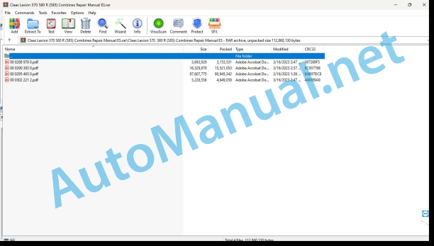
File List:
00 0288 978 0.pdf
00 0290 383 0.pdf
00 0295 465 0.pdf
00 0302 221 2.pdf
00 0288 978 0.pdf:
LEXION 770-405
Introduction
General information
Manual validity
Using the manual
Texts and figures
Division with construction group structure
Search and find
Direction signs
Abbreviations
Technicalities
Security
General information
Especially important
Danger symbols
General safety measures and accident prevention rules
Safety measures and accident prevention in combine harvesters
First aid measures
Leave the machine
Battery separator switch
Put the machine out of service
02 Gears / clutch / cardan shaft
0210 Vibration dampers
Oscillation damper
Technical instructions
Preparation for work
Disassemble
Oscillation damper
Technical instructions
Preparation for work
Disassemble
Oscillation damper
Technical instructions
Preparation for work
Disassemble
00 0290 383 0.pdf:
1. Introduction
1.1 General instructions
1.1.1 Validity of the manual
2 Feeding channel
2.1 Feeding channel
2.1.1 Renew the anti-slip strips of the HP feed channel
3 Straw discharge
3.1 Chaff spreader
3.1.1 Summary of chaff spreader / chaff draft fan LEXION 600 – 560 (Type 589 – 584)
3.1.2 Overview of the LEXION 600 – 560 Radial Spreader (Type 589 – 584)
3.2 Straw spreader
3.2.1 Summary of the straw spreader
4 Drives
4.1 Drive belts / drive chains
4.1.1 Left drive diagram (LEXION 600 with JET STREAM cleaning system)
4.1.2 Right drive diagram (LEXION 600 with JET STREAM cleaning system)
4.1.3 Left drive diagram (LEXION 580 with standard cleaning system)
4.1.4 Right drive diagram (LEXION 580 with standard cleaning system)
4.1.5 Left drive diagram (LEXION 570 with standard cleaning system)
4.1.6 Right drive diagram (LEXION 570 with standard cleaning system)
4.1.7 Left drive diagram (LEXION 570 with JET STREAM cleaning system)
4.1.8 Right drive diagram (LEXION 570 with JET STREAM cleaning system)
4.1.9 Left drive diagram (LEXION 560 – 510 with standard cleaning system)
4.1.10 Right drive diagram (LEXION 560 – 510 with standard cleaning system)
4.1.11 Remove the belt (R26)
4.1.12 Install the belt (R26)
4.1.13 Adjust the belt (R26)
4.2 Fan drive, JET STREAM LEXION 570 cleaning system
4.2.1 Summary of the fan drive (electric) from machine no. …
4.2.2 Overview of fan drive (spring loaded) from machine no. …
4.2.3 Summary of the fan drive from machine no. …
4.3 Special tool for fan drive, JET STREAM LEXION 570 cleaning system
4.3.1 Disassemble the fan drive (under spring load) from machine no. …
4.3.2 Disassemble the fan drive (under spring load) from machine no. …
4.4 Head drive
4.4.1 Belt summary (R2)
4.4.2 Remove the belt drive pulley (R2) from machine no. …
4.4.3 Summary of the belt drive pulley (R2) from machine no. …
4.4.4 Assemble the belt drive pulley (R2) from machine no. …
4.4.5 Belt summary (R3) (with headstock variator)
4.4.6 Disassemble the head variator (hydraulic) from machine no. …
4.4.7 Summary of the head drive (hydraulic) from machine no. …
4.4.8 Assemble the head variator (hydraulic) from machine no. …
4.4.9 Overview of belt (R3) (with stepped head drive)
4.4.10 Belt summary (R26)
4.4.11 Remove the belt drive pulley (R26)
4.4.12 Overview of belt drive pulley (R26)
4.4.13 Assemble the belt drive pulley (R26)
4.4.14 Remove the belt driven pulley (R26)
4.4.15 Summary of belt driven pulley (R26)
4.4.16 Assemble the belt driven pulley (R26)
4.4.17 Overview of belt tensioner pulley (R26)
4.5 Special tool for head drive
4.5.1 Assemble the belt drive pulley (R2) from machine no. …
4.5.2 Disassemble the head variator (hydraulic) from machine no. …
4.5.3 Assemble the head variator (hydraulic) from machine no. …
4.5.4 Assemble the belt drive pulley (R26)
4.5.5 Remove the belt driven pulley (R26)
4.5.6 Assemble the belt driven pulley (R26)
4.6 Drive of the straw thrower
4.6.1 Remove the belt driven pulley (R5) from machine no. …
4.6.2 Summary of the driven belt pulley (R5) from machine no. …
4.6.3 Assemble the belt driven pulley (R5) from machine no. …
4.7 Straw thrower drive special tool
4.7.1 Remove the belt driven pulley (R5) from machine no. …
5 Axles, tires
5.1 Steering axis
5.1.1 Dismantling the steering axle / CLAAS 4-TRAC axle / standard cleaning system
5.1.2 Installing the steering axle / CLAAS 4-TRAC axle, standard cleaning system
5.1.3 Dismantling the steering axle / CLAAS 4-trac axle / ACTIVE TRAC axle, JET STREAM cleaning system
5.1.4 Install the steering axle / CLAAS 4-trac axle / ACTIVE TRAC axle, JET STREAM cleaning system
5.1.5 Summary of the steering axle (10t adjustable)
5.1.6 Summary of the steering axle (9.5t adjustable)
5.1.7 Summary of the steering axle (9t adjustable)
5.1.8 Steering axle summary (9t fixed)
5.1.9 Summary of the steering axle (8.5t adjustable)
5.1.10 Summary of the steering axle (7.5t fixed / adjustable)
5.1.11 Summary of the steering axle (7t adjustable)
5.2 Drive steering axle
5.2.1 Dismantle the ACTIVE TRAC axis motor reception (11t)
5.2.2 Summary of ACTIVE TRAC axle motor reception (11t)
5.2.3 Assemble the ACTIVE TRAC axis motor reception (11t)
5.2.4 Dismantle the ACTIVE TRAC axle gear (11T)
5.2.5 Assemble the ACTIVE TRAC axle gear (11t)
5.2.6 ACTIVE TRAC axle summary (11t)
5.2.7 CLAAS 4-TRAC axle summary (11t)
5.2.8 CLAAS 4-TRAC axle summary (9t / 10t)
5.2.9 CLAAS 4-TRAC axle summary (9.5t)
5.3 Drive steering axle special tool
5.3.1 Assemble the ACTIVE TRAC axis motor reception (11t)
6 Hydraulic installation
6.1 General notes
6.1.1 Bleeding hydrostatic equipment with mechanical-hydraulic propulsion
6.1.2 Bleeding hydrostatic equipment with electro-hydraulic propulsion
6.1.3 Bleeding the CLAAS 4 – Trac system with mechanical-hydraulic propulsion
6.2 General hydraulic installation special tool
6.2.1 Bleeding hydrostatic equipment with mechanical-hydraulic propulsion
6.2.2 Bleeding hydrostatic equipment with electro-hydraulic propulsion
6.3 Hydraulic motors
6.3.1 Dismantle the radial spreader motor (241 / 242)
6.3.2 Assemble the radial spreader motor (241 / 242)
6.3.3 Dismantle the CLAAS 4-TRAC axle motor (203 / 204)
6.3.4 Assembling the CLAAS 4-TRAC axle motor (203 / 204)
6.3.5 Remove ACTIVE TRAC axle motor (2063 / 2064)
6.3.6 Assemble ACTIVE TRAC axle motor (2063 / 2064)
6.3.7 Summary of steering hydraulic cylinder (synchronized cylinder) (323)
6.4 Special tool for hydraulic motors
6.4.1 Assemble the radial spreader motor (241 / 242)
6.5 Hydraulic cylinder
6.5.1 Overview of steering hydraulic cylinder (synchronized cylinder) (323)
7 Engine
7.1 Distribution gear
7.1.1 Disassemble the distribution gear
7.1.2 Timing Gear Summary
7.2 Timing gear special tool
7.2.1 Disassemble the distribution gear
7.2.2 Dismantle the distribution gear
7.2.3 Assemble the timing gear
7.2.4 Assemble the timing gear
Alphabetical index
00 0302 221 2.pdf:
LEXION 780-405
Introduction
General information
Manual validity
Using the manual
Texts and figures
Division with construction group structure
Search and find
Direction signs
Abbreviations
Technicalities
Tightening torques
Tightening torques for normal metric threads
Tightening torques for metric fine threads
Tightening torques for hydraulic threads with adjusting ring DIN 3861
Security
General information
Especially important
Danger symbols
General safety measures and accident prevention rules
Safety measures and accident prevention in combine harvesters
First aid measures
Unloading of the harvest / unloading of the chaff
Leave the machine
Adjustment and maintenance work
Risk of injury from hydraulic fluid
Battery separator switch
Put the machine out of service
08 Drives
0841 Threshing organs drive
Driven Belt Pulley (R52)
Technical instructions
Preparation for work
special tool
Disassemble
Greasing interval
0842 Separation drive
Driven Belt Pulley (R41)
Technical instructions
Preparation for work
special tool
Disassemble
Greasing interval
John Deere Repair Technical Manual PDF
John Deere 18-Speed PST Repair Manual Component Technical Manual CTM168 10DEC07
John Deere Repair Technical Manual PDF
John Deere Parts Catalog PDF
John Deere Tractors 7500 Parts Catalog CPCQ26568 30 Jan 02 Portuguese
John Deere Repair Technical Manual PDF
John Deere Repair Technical Manual PDF
John Deere Repair Technical Manual PDF
John Deere Application List Component Technical Manual CTM106819 24AUG20
John Deere Repair Technical Manual PDF
John Deere Repair Technical Manual PDF
New Holland Service Manual PDF
John Deere Repair Technical Manual PDF

