Claas Lexion 750 Montana (C51) Combines Operator Manual FR
$50.00
- Model: Lexion 750 Montana (C51) Combines
- Type Of Manual: Operator Manual
- Language: FR
- Format: PDF(s)
- Size: 78.5 MB
File List:
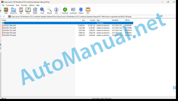
00 0291 090 4.pdf
00 0291 180 3.pdf
00 0291 230 1.pdf
00 0292 676 0.pdf
00 0292 792 0.pdf
00 0291 180 3.pdf:
LEXION 750 MONTANA
LEXION 670 MONTANA
LEXION 630 MONTANA
Contents
1 Introduction
1.1 General information
1.1.1 Validity of the notice
2 Security
2.1 General information
2.1.1 Travel mode with tilt compensation
2.2 Warning pictograms
2.2.1 Cabin / Driving position
2.2.2 Power supply organs
3 Technical characteristics
3.1 LEXION 750 / 670 / 630 MONTANA – Type C51 / C50 / C52
3.1.1 Machine equipment for technical characteristics
3.1.2 Chassis
3.1.3 Undercarriage, tire pressure
3.1.4 Undercarriage, track
3.1.5 Brake
3.1.6 Grain recovery, dimensions
3.1.7 Assembled parts / Machine casing, dimensions
4 Before first commissioning
4.1 General information
4.1.1 General warning instructions
4.1.2 Checklist for initial commissioning
4.2 Chassis
4.2.1 Remove/install the wheels
4.2.2 Overview of the steering axle
4.2.3 Place the machine on jack stands for the steering axle to swing
4.2.4 Change the setting of the drive axle from road position to working position
4.2.5 Drive axle 00 0694 642 X – adjust track width
4.2.6 Move steering axle 00 0775 540 X from transport position to working position
4.2.7 Steering axle 00 0775 540 X – adjust track width
4.2.8 Shift the steering axle 00 0769 105
4.3 Hydraulic system
4.3.1 Check / fill the front tool relief pressure accumulator.
4.4 Assembly parts / Bodywork
4.4.1 Access ladder for LEXION 670 MONTANA
4.4.2 Access ladder for LEXION 750 / 630 MONTANA
4.4.3 Pre-assemble the access ladder (LEXION 750 / 670 / 630 MONTANA)
4.4.4 Install the access ladder (LEXION 750 / 670 / 630 MONTANA)
4.4.5 Install the weights for the folding front tools
5 Before each commissioning
5.1 General information
5.1.1 General warning instructions
5.1.2 Commissioning checklist
6 Install/remove the front tool
6.1 General information
6.1.1 General warning information, before initial commissioning
6.2 Hydraulic system
6.2.1 Install the multiple coupling
6.2.2 Remove the multiple coupling
7 Overview of adjustment elements
7.1 General information
7.1.1 General warning information, before initial commissioning
7.2 Cabin / Driving position
7.2.1 Overview of the driving position
7.2.2 Control console
7.2.3 MONTANA control control panel
8 Road driving and transport
8.1 General information
8.1.1 General warning information, before initial commissioning
8.2 Transmission / Clutch / Cardan shaft
8.2.1 Differential lock
8.3 Chassis
8.3.1 Submit a report
8.3.2 MONTANA command
8.3.3 Controlling MONTANA functions
8.3.4 Connect the MONTANA control
8.3.5 Lower the machine completely before traveling on the road
8.3.6 Bring the machine to neutral position
8.3.7 Manual axle control
8.3.8 Manual control of the front tool
8.3.9 Automatic service
8.3.10 Change cutting angle/tilt (cross regulation) automatic service
8.4 Brake
8.4.1 Connect the parking brake
8.4.2 Deactivate the parking brake
8.5 Assembly parts / Bodywork
8.5.1 Fold down the steps of the access ladder
8.5.2 Pivoting the access ladder
9 Settings for work
9.1 General information
9.1.1 General safety instructions, work settings
9.2 Conveyor
9.2.1 Adjusting the feed chain in height
9.3 Threshing bodies
9.3.1 Beater hatch
10 Incidents and remedies
10.1 General information
10.1.1 General warning tips, fault and solution
10.2 Transmission / Clutch / Cardan shaft
10.2.1 Mechanically position the gearbox in neutral
10.3 Brake
10.3.1 Mechanically release the parking brake
10.4 Chassis
10.4.1 Undercarriage, failure and solution
10.5 Electrical/electronic system
10.5.1 MONTANA command, failure and solution
10.6 Power group
10.6.1 Power group, fault and solution
11 Maintenance
11.1 General information
11.1.1 General safety instructions regarding maintenance
11.2 Maintenance tables
11.2.1 Maintenance intervals
11.3 Lubricant tables
11.3.1 Lubricants
11.4 Lubrication plan
11.4.1 Lubrication points – 100 h left side
11.4.2 Lubrication points – 100 h right side
11.4.3 Lubrication points – 500 h left side
11.4.4 Lubrication points – 500 h right side
11.5 Chassis
11.5.1 Check the oil level of the differential and axle support
11.5.2 Drain the oil from the differential and axle support
11.5.3 Pour oil into the differential and axle support
11.5.4 Check the oil level of the wheel connecting rods
11.5.5 Drain the oil from the wheel connecting rods
11.5.6 Pour oil from the wheel connecting rods
11.5.7 Wheel connecting rods, lubrication instructions for slewing rings
11.5.8 Wheel connecting rods, basic linkage adjustment
11.5.9 Check the oil level of the drive axle gearbox
11.5.10 Change the oil from the drive axle gearbox
11.5.11 Pour oil into the drive axle gearbox
11.5.12 Check the oil level of the transaxle gearbox
11.5.13 Drain the oil from the axle gearbox
11.5.14 Pour oil into transaxle
11.6 Power group
11.6.1 MONTANA feed channel – setting feed channels
11.6.2 Basic adjustment of the cutting angle linkage
11.6.3 Basic adjustment of the cross control linkage
11.6.4 Basic adjustment of cross position linkage
00 0291 230 1.pdf:
LEXION 770 – 620
Contents
1 Introduction
1.1 General information
1.1.1 Validity of the notice
2 Overview of adjustment elements
2.1 Cabin / Driving position
2.1.1 Multifunction handle
00 0292 676 0.pdf:
LEXION 770 – 620TUCANO 470 – 320
Contents
1 About this user manual
1.1 General information
1.1.1 Validity of the notice
1.1.2 Symbols and instructions
2 Controls and displays
2.1 Cabin / Driving position
2.1.1 CEBIS control panel
2.2 CEBIS display
2.2.1 CEBIS general advice
2.2.2 Overview of the displacement indicator
2.2.3 Overview of the displacement indicator
2.2.4 Overview of the harvest indicator
2.2.5 CRUISE PILOT crop indicator overview
2.2.6 CEBIS direct menu overview
2.2.7 Respect CEBIS error code information
Respect type of error code information
Respect the structure of error code information
Classify error code information
View alarm history
View active alarms
2.2.8 Message box symbols
2.2.9 CEBIS direct menu
2.2.10 HOTKEY direct menu
2.2.11 Quick access menu
2.2.12 Main menu
2.2.13 Front tool menu
2.2.14 Driving menu
2.2.15 AUTO PILOT menu
2.2.16 Machine settings menu
2.2.17 Harvested product settings menu
2.2.18 Counter Menu
2.2.19 Maintenance menu
2.2.20 CEBIS menu
00 0292 792 0.pdf:
LEXION 770 – 670
Contents
1 About this user manual
1.1 General information
1.1.1 Validity of the notice
1.1.2 Symbols and instructions
2 Controls and displays
2.1 Cabin / Driving position
2.1.1 CEBIS control panel
2.2 CEBIS display
2.2.1 CEBIS general advice
2.2.2 Overview of the displacement indicator
2.2.3 Overview of the displacement indicator
2.2.4 Overview of the harvest indicator
2.2.5 CRUISE PILOT crop indicator overview
2.2.6 CEBIS direct menu overview
2.2.7 Respect CEBIS error code information
Respect type of error code information
Respect the structure of error code information
Classify error code information
View alarm history
View active alarms
2.2.8 Message box symbols
2.2.9 CEBIS direct menu
2.2.10 HOTKEY direct menu
2.2.11 Quick access menu
2.2.12 Main menu
2.2.13 Front tool menu
2.2.14 Driving menu
2.2.15 AUTO PILOT menu
2.2.16 Machine organs menu
2.2.17 Harvested Product Menu
2.2.18 Counter Menu
2.2.19 Maintenance menu
2.2.20 CEBIS menu
John Deere Repair Technical Manual PDF
John Deere Repair Technical Manual PDF
John Deere Repair Technical Manual PDF
John Deere Diesel Engines POWERTECH 2.9 L Component Technical Manual CTM126 Spanish
John Deere Repair Technical Manual PDF
John Deere Repair Technical Manual PDF
John Deere 16, 18, 20 and 24HP Onan Engines Component Technical Manual CTM2 (19APR90)
New Holland Service Manual PDF
John Deere Repair Technical Manual PDF
John Deere Repair Technical Manual PDF
John Deere Repair Technical Manual PDF
John Deere Parts Catalog PDF
John Deere Tractors 7500 Parts Catalog CPCQ26568 30 Jan 02 Portuguese

