Claas Lexion 780-770 (C76) Combines Technical System EN
$300.00
- Model: Lexion 780-770 (C76) Combines
- Type Of Manual: Technical System
- Language: EN
- Format: PDF(s)
- Size: 258 MB
File List:
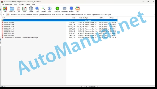
00 0288 556 0.pdf
00 0298 055 3.pdf
00 0300 851 4.pdf
00 0302 343 1.pdf
00 0302 565 2.pdf
00 0303 815 1.pdf
00 0305 863 0.pdf
CHP-numbers for connectors CLAAS HARNESS PARTS.pdf
00 0288 556 0.pdf:
PERKINS 2206D – E13 TA
Table of contents
CCN explanation
CCN (CLAAS Component Number)
Electric system standard
Overview
CCN (CLAAS Component Number)
Introduction
Validity of manual
Validity of manual
Safety rules
Safety and hazard information
General information
Important!
Hazard signs
Signal word
Regulations for avoiding accidents with personal injuries
Testing, adjusting and repair work
Engine operation
Suspended loads
Working on piping and hoses
Work on the Common Rail System
Working on the electric system
Working on the hydraulic system
Electric welding
Painting work
Working with urea solution
Information on how to avoid damage and premature wear
Liability limitation
Shutting down and storage
Regulations for avoiding health and environmental damage
Precautionary measures for protection against health and environmental damage
Disposal of operating utilities and auxiliary operating utilities
Information for working on the diesel engine
Accident protection
Cleanliness
Installation instructions
Engine overhaul
Putting into operation after an engine overhaul
First-aid measures
List of abbreviations
Glossary
Example: Pulse Width Modulation (PWM)
01 Engine
0102 Complete component
Complete component
Engine components – turbocharger side
Engine components – left side
Product Description
Engine Specifications
Identification plates of Perkins 2206D-E13TA diesel engine
Plate Locations and Film Locations
Technical specifications Perkins 2206D-E13TA diesel engine
Engine Specifications
General Information
Introduction
0110 Engine housing
Basic engine
Cylinder crankcase
Description of function
Camshaft
0120 Cylinder head / Valves / Idler gear
Cylinder head – Valves – Gearwheels drive
Valve system components
Valve system components
Description of function
Gear Group (Front) – Time
Description of function
Crankcase Breather
0125 Injection / Fuel system
Cleanliness of fuel system components
Cleanliness of the engine
Working environment
Tools that have to be used to achieve cleanliness when working on the fuel injection system: Warranty condition.
New Components
Refuelling
Injection system / fuel system
Fuel system (figure serves as an example)
Description of function
Low-pressure fuel system
Description of function
Unit Injector Mechanism
Unit Injector
MEUI Injector (Pre-injection)
MEUI Injector (Injection)
MEUI Injector (End of injection)
MEUI Injector (Fill)
0130 Lubricating oil system
Lubricating oil system
Lubrication system schematic
Right side view of engine
Description of function
Oil Flow Through The Lubrication System
Description of function
Interior of cylinder block
0135 Cooling system
Cooling System
Coolant Flow
Description of function
Right side view of engine
Temperature Regulator Housing
Coolant for Air Compressor (If Equipped)
0140 Exhaust system
Exhaust system
Air inlet and exhaust system schematic
Description of function
Air inlet and exhaust system
Turbocharger
0155 Engine control
Diesel engine monitoring / speed adjustment (Example: XERION TYP 782)
Measured values table
Description of function
Diesel engine monitoring system operation
Electronic Control System Components (Illustration 1)
Electronic Control System Components (Illustration 2)
Description of function
Starting the Engine
Cold Mode Operation
0197 Test/Measurement/Setting
Fuel System – Inspect
Air in Fuel – Test
Test air bubbles in the fuel
Electronic Unit Injector – Adjust
Injector Mechanism
Electronic Unit Injector – Test
Injector Trim File – Install
Diagnostic Trouble Codes for Injector Data Incorrect
Figure of injector numbers
Install the injector trim file
Finding Top Center Position for No. 1 Piston
Timing hole
Fuel Quality – Test
Fuel System – Prime
Prime pump
Fuel System Pressure – Test
Checking Fuel Pressure
A typical example of a secondary fuel filter base
Fuel transfer pump (side view)
Air Inlet and Exhaust System – Inspect
Air Inlet Restriction
Air cleaner test
Exhaust Restriction
Exhaust back pressure test
Turbocharger – Inspect
Inspection of the Turbine Wheel and the Turbine Housing
Inspection of the Wastegate
Exhaust Temperature – Test
Aftercooler – Test
Engine Crankcase Pressure (Blowby) – Test
Compression – Test
Engine Valve Lash – Inspect / Adjust
Valve Lash Adjustment
Engine Oil Pressure – Test
Measuring Engine Oil Pressure
Oil gallery plug
Reasons for Low Engine Oil Pressure
Reason for High Engine Oil Pressure
Engine Oil Pump – Inspect
Excessive Bearing Wear – Inspect
Excessive Engine Oil Consumption – Inspect
Increased Engine Oil Temperature – Inspect
Cooling System – Check (Overheating)
Cooling System – Inspect
Cooling System – Test
Boiling point of water
Checking the Filler Cap
Typical schematic of filler cap
Testing The Radiator And Cooling System For Leaks
Test For The Water Temperature Gauge
Water manifold assembly
Water Temperature Regulator – Test
Water Pump – Test
Vibration Damper – Check
Viscous Vibration Damper
CAN Data Link – Test
Diagnostic Trouble Codes for the CAN Data Link Circuit
The following background information is relevant for this measure
Schematic CAN J1939 Network. Example XERION Typ 782
Connectors for the Engine (ECM) A015
Electrical Power Supply – Test
Diagnostic Codes Table
Schematic P1 ECM Connector
Ether Starting Aid – Test
Diagnostic Codes Table
Schematic of the ether injection system
Ether starting aid group
Injector Solenoid – Test
Diagnostic Trouble Codes for the Circuit for the Injector Solenoids
Background Information
Diagnostic Tests on the Electronic Service Tool (CDS)
Electronic unit injector
Schematic of the circuit for the injector solenoids
P2 ECM connector
Sensor Calibration Required – Test
Diagnostic Trouble Codes for Sensor Calibration
Sensor Signal (Analog, Active) – Test
Diagnostic Trouble Codes for the Analog, Active Sensors
Schematic for the (Analog, Active) pressure sensors
J2 / P2 ECM connector
Connectors for the sensors
Sensor Signal (Analog, Passive) – Test
Diagnostic Trouble Codes for the Analog, Passive Sensors
Terminal locations at the connector for the passive analog sensors
Schematic for the (Analog, Passive) sensors
P2 terminations for the engine temperature sensors
Sensor Supply – Test (5 V Supply)
Sensor power supply diagnostic trouble codes
System Operation
Schematic for the 5 V supply
J2 / P2 ECM connector
Connectors for the sensors
Speed/Timing – Test
Diagnostic Trouble Codes for the Engine Speed/Timing Sensors
Function Description
Schematic for the speed/timing sensors
Crank shaft speed/timing sensor
Camshaft speed/timing sensor
Terminal locations at the connector for the speed/timing sensors
Timing – Calibrate
Diagnostic Trouble Codes
Function Description
Schematic for the transducer install
Illustration timing calibrate
Electrical Connectors – Inspect
Connector Illustration. Detail A
Diagram for the installation of a connector plug (typical example)
Seal for a three-pin connector
Seal for the ECM connector
Receptacle lock wedge
Diagramm for testing Pin retention
Check the Allen Head Screws on the Connectors
Allen head screw for the 120 pin ECM connector
Allen head screw for the 70 pin ECM connector
Allen head screw for the 40 pin customer connector and the 70 pin customer connector
Test ECM Mode
Replacing the engine control module (ECM)
Configuration Parameters
Codes That Relate to Configuration Parameters
Function Description
ECM Software – Install
Codes That Relate to Configuration Parameters
Function Description
0198 Problem / Remedy
Coolant Contains Fuel
Introduction
Probable causes
Recommended actions
Coolant contains oil
Introduction
Probable causes
Recommended actions
Coolant temperature is high
Introduction
Diagnostic trouble codes for high coolant temperature
Probable causes
Recommended actions
Cylinder is noisy
Probable causes
Recommended actions
Engine cranks but does not start
Recommended actions
Engine does not crank
Recommended actions
Engine Has Early Wear
Probable causes
Recommended actions
Engine Has Mechanical Noise (Knock)
Probable causes
Recommended actions
Engine Misfires, Runs Rough or is Unstable
Probable causes
Recommended actions
Engine Overspeeds
Diagnostic Trouble Codes for Engine Overspeed
Probable causes
Recommended actions
Engine Shutdown Occurs Intermittently
Probable causes
Recommended actions
Engine Stalls at Low RPM
Probable causes
Recommended actions
Engine Top Speed is Not Obtained
Probable causes
Recommended actions
Engine Vibration Is Excessive
Probable causes
Recommended actions
Exhaust Has Excessive Black Smoke
Probable causes
Recommended Actions
Exhaust Has Excessive White Smoke
Probable causes
Recommended actions
Exhaust System Contains Oil
Probable causes
Recommended actions
Exhaust Temperature Is High
Probable causes
Recommended actions
Fuel Consumption Is Excessive
Probable causes
Recommended actions
Fuel Pressure Is High
Probable causes
Diagnostic trouble codes
Recommended actions
Fuel supply lines
Return fuel line
Return fuel pressure regulator (5)
Typical fuel transfer pump. Relief valve (6)
Fuel Pressure Is Low
Probable causes
Diagnostic trouble codes
Recommended actions
Secondary fuel filter base
Fuel return pressure regulator
Fuel Temperature Is High
Probable causes
Diagnostic Trouble Codes for Fuel Temperature Is High
Recommended actions
Fuel supply lines
Return fuel line
Return fuel pressure regulator (5)
Intake Manifold Air Temperature Is High
Diagnostic Trouble Codes for High Intake Manifold Air Temperature
Oil Consumption is Excessive
Probable causes
Recommended actions
Oil Contains Coolant
Probable causes
Recommended actions
Oil Contains Fuel
Measuring Fuel Dilution
Probable causes
Recommended actions
Oil Pressure is Low
Diagnostic codes for low engine oil pressure
Probable causes
Recommended actions
Power is Intermittently Low or Power Cutout is Intermittent
Probable causes
Recommended actions
Valve Lash is Excessive
Probable causes
Recommended actions
Valve Rotator or Spring Lock Is Free
10 Electrical / Electronic equipment
1012 Modules / sensors
Module A015 – PERKINS 2206D – E13TA
Engine ECM A015
Module A015 – (ECM) Engine Control Module
Overview of modules – PERKINS 2206D – E13TA
Connectors for the Engine (ECM) A015
Sensors / actuators – PERKINS 2206D – E13TA
Engine electrics overview
Key to diagram
Electronic Control System Components (Illustration 1)
Electronic Control System Components (Illustration 2)
92 Diagnosis
9220 Error codes engine (J1939)
FMI failure code (Failure Mode Indicator)
FMI fault code (Failure Mode Indicator) PERKINS
FMI 00 (Signal too high)
FMI 01 (Signal too low)
FMI 02 (Erratic signal)
FMI 03 (Voltage too high)
FMI 04 (Voltage too low)
FMI 05 (Current too low)
FMI 06 (Current too high)
FMI 07 (Mechanical fault)
FMI 08 (Faulty frequency signal)
FMI 09 (Communication fault)
FMI 10 (Signal changes too quickly)
FMI 11 (Multiple fault)
FMI 12 (ECU defective)
FMI 13 (Signal outside of calibration range)
FMI 16 (Parameter not available)
FMI 17 (No reply from ECU)
FMI 18 (Power supply fault)
FMI 19 (Software conditions not met)
Fault codes
Diesel engine fault codes – J 1939 / PERKINS / 2206D – E13TA
Diagnostic Trouble Codes
Event Codes
9295 Measuring devices
Connecting CDS
Home screen after communication with the CDS
CDS features
Module overview
Engine control
Connecting CDS
Module diagnostics
Engine tests
GENERAL 1: How to find the engine tests
GENERAL 2: Selection menu (engine tests)
Injector solenoid test (0125)
Test description
Cylinder Cutout Test (0155)
Test description
Test Module Outputs (0155)
Setting of Module Outputs and Valves
Position of components
Electric system
A Terminal / modules
B Sensors
Y Solenoid coils
00 0302 343 1.pdf:
PROFI CAM 3
Table of contents
General information
Marking of warnings and hazard prevention notes
First-aid measures
CCN explanation
CCN (CLAAS Component Number)
Electric system standard
Overview
Hydraulic system standard
Overview
CCN (CLAAS Component Number)
10 Electrical / Electronic equipment
1030 Board computer / Indicators
Camera system
Description of function
1097 Testing / Measuring / Adjusting
Testing / measuring / adjusting the PROFI CAM
Checking the fuse in the video channel select box (C102)
Testing the video camera connector (C055)
1098 Fault / remedy
Fault / remedy PROFI CAM
The video monitor (C101) shows no image or cannot be switched on (indicator light fails to light up)
Video monitor (C102) displays a blue image either permanently or temporarily
The video monitor image is blurred
Replacing the fuse in the video channel select box (C102)
Connection and connecting cable with video camera (C055)
00 0302 565 2.pdf:
Sensor system
Table of contents
CCN explanation
CCN (CLAAS Component Number)
Electric system standard
Overview
Hydraulic system standard
Overview
CCN (CLAAS Component Number)
Introduction
Safety rules
Safety and hazard information
10 Electrical / Electronic equipment
1097 Testing / Measuring / Adjusting
Test report of the angle sensor (0011780.x)
Application of test report
Required tools
Test report of the angle sensor (0011780.x)
Testing / Measuring / Adjusting of angle sensor (0011780.x)
1. Reason for test
2. Mechanical test of angle sensor
3. Electric test with CDS
4. Electric test with multimeter
5. Mechanical test of connecting cable
Completing the machine
Test report of position and speed sensors
Application of test report
Required tools
Sensor variants
Part numbers of speed sensors
Part number of position sensor
Test report of position and speed sensors
Testing / measuring / adjusting of position and speed sensors
1. Reason for test
2. Mechanical test
3. Electric test with CDS
4a. Installation dimensions
Check of installation dimension
Installation dimensions of gearbox speed sensor (0011 799.x) and cam speed sensor (0011 810.x)
Installation dimension of position sensor (0011 815.x)
4b. Installation position
Centring of sensor
Metal-free zone
5. Electric test with multimeter
Voltage measurement
Direction of rotation and speed sensor (0011 605.x)
Measured values table
6. Mechanical test of connecting cable
Completing the machine
Test report of the urea sensor (00 0773 207 x)
Application of test report
Required tools
Parts number of the urea sensor
Test report of the urea sensor
Testing / measuring / adjusting urea sensor
1. Reason for test
2. Mechanical test
3. Mechanical test of connecting cable
4. Electric test with multimeter
5. Component test with the CDS
00 0305 863 0.pdf:
LEXIONJAGUARXERION
Table of contents
Introduction
Notes on the manual
Validity of manual
Information about this Technical Systems Manual
Identifying warnings
Hazard signs
Signal word
01 Engine
0125 Injection / Fuel system
Injection / fuel system
Required tools and aids
Line valves for connecting to the engine
Valves and adapters for tank feed and return lines
Measuring setup (possible variant)
Test procedure
A – Leakage test of tank return line and possibly of tank suction line
B – Leakage test of feed lines (possibly including fuel sediment filter)
C – Test of non-return valve in the line (if provided)
D – Leakage test of return lines (possibly including the fuel cooler)
E – Leakage test of fuel sediment filter
F – Leakage test of engine
Steps 1 – 3
Fuel diagrams
Remarks about the circuit diagrams
LEXION fuel diagram
Key to diagram
JAGUAR with Mercedes-Benz OM47x LA
Key to diagram
JAGUAR with MAN D2862 (V12)
Key to diagram
CHP-numbers for connectors CLAAS HARNESS PARTS.pdf:
CLAAS HARNESS PARTS
Table of contents
10 Electrical / Electronic equipment
1081 Overview of connectors
CLAAS HARNESS PARTS (CHP)
John Deere Repair Technical Manual PDF
John Deere Repair Technical Manual PDF
John Deere POWERTECH E 4.5 and 6.8 L Diesel Engines TECHNICAL MANUAL 25JAN08
John Deere Repair Technical Manual PDF
John Deere Repair Technical Manual PDF
John Deere Repair Technical Manual PDF
John Deere Diesel Engines PowerTech 4.5L and 6.8L – Motor Base Technical Manual 07MAY08 Portuguese
John Deere Repair Technical Manual PDF
John Deere Repair Technical Manual PDF
John Deere Repair Technical Manual PDF
John Deere Repair Technical Manual PDF
John Deere Diesel Engines POWERTECH 2.9 L Component Technical Manual CTM126 Spanish
John Deere Repair Technical Manual PDF
John Deere 18-Speed PST Repair Manual Component Technical Manual CTM168 10DEC07

