Claas Liner 450 (G12) Swathers Operator Manual EN
$50.00
- Model: Liner 450 (G12) Swathers
- Type Of Manual: Operator Manual
- Language: EN
- Format: PDF(s)
- Size: 56.3 MB
File List:
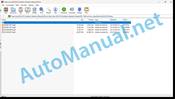
00 0291 491 3.pdf
00 0291 541 3.pdf
00 2348 408 0.pdf
00 2348 427 0.pdf
00 0291 491 3.pdf:
LINER 450LINER 420LINER 370
Table of contents
1 Introduction
1.1 Notes on the manual
1.1.1 Validity of the manual
1.1.2 Information about this Operator’s Manual
1.1.3 Symbols and notes
1.1.4 Optional equipment
1.1.5 Qualified specialist workshop
1.1.6 Maintenance notes
1.1.7 Warranty notes
1.1.8 Spare parts and technical questions
1.2 Intended use
1.2.1 Intended use
1.2.2 Reasonably foreseeable misuse
2 Safety
2.1 Identifying warnings
2.1.1 Hazard signs
2.1.2 Signal word
2.2 Safety rules
2.2.1 Importance of Operator’s Manual
2.2.2 Observe the safety decals and warnings
2.2.3 Requirements for all persons working with the machine
2.2.4 Children in danger
2.2.5 Hazard areas
2.2.6 Staying between the tractor and the machine
2.2.7 Persons riding on the machine
2.2.8 Hitching the tractor to the machine
2.2.9 Risk of injury from rotating shafts
2.2.10 Structural changes
2.2.11 Optional equipment and spare parts
2.2.12 Control of the machine while it is running
2.2.13 Only use once properly put into operation
2.2.14 Technical condition
2.2.15 Danger from damage to the machine
2.2.16 Complying with technical limit values
2.2.17 Danger from machine parts running on
2.2.18 Keeping the safety devices functional
2.2.19 Personal protective equipment
2.2.20 Wearing suitable clothing
2.2.21 Removing dirt and loose objects
2.2.22 Preparing the machine for road travel
2.2.23 Risks when driving on the road and in the field
2.2.24 Parking the machine safely
2.2.25 Unsupervised parking
2.2.26 Unsuitable operating utilities
2.2.27 Safe handling of operating and auxiliary utilities
2.2.28 Fire prevention
2.2.29 Environmental protection and disposal
2.2.30 Lethal electrocution from overhead lines
2.2.31 Behaviour in case of voltage flash-over from overhead lines and when lightning strikes
2.2.32 Pressurised fluids
2.2.33 Hot surfaces
2.2.34 Work on the machine only after shutting down
2.2.35 Maintenance work and repairs
2.2.36 Raised machine parts and loads
2.2.37 Danger from welding work
2.3 Safety marking
2.3.1 Layout of safety decals
2.3.2 Safety decals on the machine
3 Machine description
3.1 Overview and method of operation
3.1.1 Overview
3.1.2 Functions
3.2 Optional machine equipment
3.2.1 Sensing wheel on the headstock*
3.2.2 Hydraulically folding safety frames*
3.2.3 Hydraulic rotor height adjustment*
3.2.4 Fourth tine*
3.2.5 Warning signs*
3.2.6 Illuminated warning signs*
3.2.7 Warning signs: Italy*
3.2.8 Legal equipment: France*
3.2.9 SMV triangle*
3.2.10 Lighting adapter for USA*
3.3 Identification plates and identification numbers
3.3.1 Machine identification plate
3.4 Information on the machine
3.4.1 Stickers on the machine
4 Operating and display elements
4.1 Controls
4.1.1 Swathing rotor
4.1.2 Protective frame
5 Technical specifications
5.1 LINER 450
5.1.1 Dimensions
5.1.2 Weights
5.1.3 Requirements for the tractor
5.1.4 Version
5.1.5 Tyre pressure
5.1.6 Noise level
5.1.7 Lubricants
5.2 LINER 420
5.2.1 Dimensions
5.2.2 Weights
5.2.3 Requirements for the tractor
5.2.4 Version
5.2.5 Tyre pressure
5.2.6 Noise level
5.2.7 Lubricants
5.3 LINER 370
5.3.1 Dimensions
5.3.2 Weights
5.3.3 Requirements for the tractor
5.3.4 Version
5.3.5 Tyre pressure
5.3.6 Noise level
5.3.7 Lubricants
6 Machine preparation
6.1 Adapting the tractor
6.1.1 Checking the ballasting of the tractor
Calculating the minimum front ballast
Calculating the minimum rear ballast
Calculating the actual front axle load
Calculating the actual total weight
Calculating the actual rear axle load
Calculation table
6.1.2 Calculating the minimum front ballast
6.1.3 Calculating the minimum rear ballast
6.1.4 Calculating the actual front axle load
6.1.5 Calculating the actual total weight
6.1.6 Calculating the actual rear axle load
6.1.7 Calculation table
6.1.8 Checking the protective guard on the tractor PTO shaft
6.2 Switching off and securing the machine
6.2.1 Switching off and securing the tractor and machine
6.2.2 Securing the raised machine
6.3 Adapting the machine
6.3.1 Universal drive shaft – checking the length
6.3.2 Universal drive shaft – Adapting the length
6.3.3 Fitting the universal drive shaft to the machine
6.3.4 Adjusting the inclination of the rotor chassis
6.4 Hitching the machine
6.4.1 Hitching up the headstock
6.4.2 Installing the universal drive shaft
6.4.3 Raising the stand
6.4.4 Connecting the hydraulic hose lines for the hydraulically folding safety frames*
6.4.5 Connecting the hydraulic lines of the hydraulic rotor height adjustment*
6.4.6 Connecting the lighting cable
6.4.7 Stowing the wheel chock
6.5 Unhitching the machine
6.5.1 Securing the machine against rolling away
6.5.2 Setting the stand down
6.5.3 Disconnecting the lighting cable
6.5.4 Disconnect hydraulic hoses from hydraulically folding safety frames*
6.5.5 Disconnecting the hydraulic lines from the hydraulic rotor height adjustment*
6.5.6 Removing the universal drive shaft
6.5.7 Unhitching the headstock
6.6 Prepare road travel
6.6.1 General safety precautions
6.6.2 Pushing the windrowing rubber to the inside
6.6.3 Folding the safety frame up
6.6.4 Swinging up the hydraulic folding safety frames*
6.6.5 Closing the shut-off tap on the hydraulically folding safety frames*
6.6.6 Removing the tine bars
6.6.7 Removing the tine bars
6.7 Preparing fieldwork
6.7.1 Installing the tine bars
6.7.2 Installing the tine bars
6.7.3 Swinging the safety frame down
6.7.4 Opening the shut-off tap on the hydraulically folding safety frames*
6.7.5 Swing down hydraulically foldable safety frames*
6.8 Loading the machine
6.8.1 Lifting the machine
7 Operation
7.1 Driving on the road
7.1.1 Driving on public roads
7.2 Fieldwork settings
7.2.1 Adjusting the swathing rotors
7.2.2 Adjusting the sensing wheel* on the headstock
7.2.3 Adjusting the swathing curtain
Adjusting the swath width
7.2.4 Setting the working height
Setting the working height with the crank
Adjusting the working height with the hydraulic rotor height adjustment*
7.2.5 Checking the working height
7.3 Fieldwork
7.3.1 Swathing
7.3.2 Adapting the PTO shaft speed
8 Faults and remedies
8.1 Chassis
8.1.1 Changing a wheel on the swathing rotor chassis
8.2 Electric and electronic system
8.2.1 Defective incandescent lamps*
9 Maintenance
9.1 Maintenance interval overview
9.1.1 Before the harvest
9.1.2 After the first 10 operating hours
9.1.3 After the first 50 operating hours
9.1.4 Every 20 operating hours
9.1.5 Every 50 operating hours
9.1.6 Every 500 operating hours or annually
9.1.7 As needed
9.1.8 After the harvest
9.2 Gearbox
9.2.1 Checking the gearbox for leaks
9.2.2 Swathing gearbox: Checking the oil level
9.2.3 Swathing gearbox: Changing the oil
9.2.4 Swathing gearbox: Checking the oil level
9.2.5 Swathing gearbox: Changing the oil
9.2.6 Swathing gearbox: Tighten the bolts
On the bolted joint between frame and swathing gearbox:
On the swathing gearbox:
9.3 Universal drive shaft
9.3.1 Servicing the universal drive shafts
9.3.2 Checking the overload clutch
9.4 Chassis
9.4.1 Check the tyre pressure
9.4.2 Changing a wheel on the rotor chassis
9.4.3 Changing the castor guide wheel*
9.4.4 Check the wheel nuts on the swathing rotor chassis
9.4.5 Check the castor guide wheel* nut
9.5 Hydraulic system
9.5.1 Checking the hydraulic hoses
9.6 Rotor
9.6.1 Checking the spring brackets
9.6.2 Checking the tines
9.6.3 Preventing frost damage
9.7 Assembly parts and machine body
9.7.1 Clean the machine
9.7.2 Preserve the machine
9.7.3 Check the fittings
9.8 Lubrication plan
9.8.1 Lubrication points every 20 operating hours
9.8.2 Lubrication points every 50 operating hours
10 Putting out of operation and disposal
10.1 General information
10.1.1 Putting out of operation and disposal
11 EC declaration of conformity
11.1 LINER 450 / LINER 420 / LINER 370
11.1.1 EC declaration of conformity
12 Technical terms and abbreviations
12.1 Terms and explanations
12.1.1 Abbreviations
12.1.2 Technical terms
00 0291 541 3.pdf:
LINER 450 TLINER 370 T
Table of contents
1 To this Operator’s Manual
1.1 Notes on the manual
1.1.1 Validity of the manual
1.1.2 Information about this Operator’s Manual
1.1.3 Symbols and notes
1.1.4 Optional equipment
1.1.5 Qualified specialist workshop
1.1.6 Notes on warranty
1.1.7 Spare parts and technical questions
1.2 Intended use
1.2.1 Intended use
1.2.2 Reasonably foreseeable misuse
2 Safety
2.1 Identifying warnings
2.1.1 Hazard signs
2.1.2 Signal word
2.2 Safety rules
2.2.1 Importance of Operator’s Manual
2.2.2 Observing safety decals and warnings
2.2.3 Requirements for all persons working with the machine
2.2.4 Children in danger
2.2.5 Hazard areas
2.2.6 Staying between the tractor and the machine
2.2.7 Persons riding on the machine
2.2.8 Hitching the tractor to the machine
2.2.9 Risk of injury from rotating shafts
2.2.10 Structural changes
2.2.11 Optional equipment and spare parts
2.2.12 Control of the machine while it is running
2.2.13 Only use once properly put into operation
2.2.14 Technical condition
2.2.15 Danger resulting from damage to the machine
2.2.16 Complying with technical limit values
2.2.17 Danger from machine parts running on
2.2.18 Keeping the safety devices functional
2.2.19 Personal protective equipment
2.2.20 Wearing suitable clothing
2.2.21 Removing dirt and loose objects
2.2.22 Preparing the machine for road travel
2.2.23 Hazards when driving on the road and in the field
2.2.24 Parking the machine safely
2.2.25 Unsupervised parking
2.2.26 Unsuitable operating materials
2.2.27 Safe handling of operating materials and auxiliary materials
2.2.28 Environmental protection and disposal
2.2.29 Fire prevention
2.2.30 Lethal electrocution from overhead lines
2.2.31 Behaviour in case of voltage flash-over from overhead lines and when lightning strikes
2.2.32 Liquids under pressure
2.2.33 Hot surfaces
2.2.34 Only carry out work on the machine when it is stopped
2.2.35 Maintenance operations and repairs
2.2.36 Raised machine parts and loads
2.2.37 Danger from welding work
2.3 Safety marking
2.3.1 Layout of safety decals
2.3.2 Safety decals on the machine
3 Machine description
3.1 Overview and method of operation
3.1.1 Machine overview
3.1.2 Function of machine
3.2 Optional equipment
3.2.1 Front sensing wheel*
3.2.2 Hydraulically folding safety frames*
3.2.3 Parallelogram drawbar*
3.2.4 Warning signs*
3.2.5 Illuminated warning signs*
3.2.6 Warning signs: Italy*
3.2.7 Legal technical equipment for the European Union*
3.2.8 SMV triangle*
3.3 Identification plates and vehicle identification number
3.3.1 Machine identification plate
3.3.2 Machine identification plate
3.4 Information on the machine
3.4.1 Stickers on the machine
4 Operating and display elements
4.1 Controls
4.1.1 Hydraulic hose
4.1.2 Drawbar
4.1.3 Swathing rotor and safety frame
5 Technical specifications
5.1 LINER 450 T
5.1.1 Dimensions
5.1.2 Weights
5.1.3 Requirements for the tractor
5.1.4 Noise level
5.1.5 Version
5.1.6 Tyre size
5.1.7 Tyre pressure
5.1.8 Lubricants
5.2 LINER 370 T
5.2.1 Dimensions
5.2.2 Weights
5.2.3 Requirements for the tractor
5.2.4 Noise level
5.2.5 Version
5.2.6 Tyre size
5.2.7 Tyre pressure
5.2.8 Lubricants
6 Machine preparation
6.1 Switching off and securing the machine
6.1.1 Switching off and securing the tractor and machine
6.1.2 Securing the raised machine
6.2 Adapting the tractor
6.2.1 Checking the protective guard on the tractor PTO shaft
6.3 Adapting the machine
6.3.1 Checking the universal drive shaft length
Shortest working position of the universal drive shaft
Longest working position of the universal drive shaft
6.3.2 Adapting the universal drive shaft length
6.3.3 Fitting the universal drive shaft to the machine
6.3.4 Adjusting the inclination of the rotor chassis
Basic settings of right swathing rotor
Basic settings of left swathing rotor
Changing the inclination
6.3.5 Mounting the linkage drawbar on the drawbar
6.4 Hitching the machine
6.4.1 Removing the safety lock*
6.4.2 Hitching the linkage drawbar up to the machine
6.4.3 Raising the stand
6.4.4 Pinning the stand in a different location
6.4.5 Pinning the stand in a different location
6.4.6 Installing the universal drive shaft
6.4.7 Fitting the safety chain*
6.4.8 Connecting the hydraulic hose
6.4.9 Connecting the hydraulic hose lines for the hydraulically folding safety frames*
6.4.10 Connecting the lighting cable
6.4.11 Stowing the wheel chocks*
6.5 Unhitching the machine
6.5.1 Positioning the wheel chocks* under the wheels
6.5.2 Disconnecting the lighting cable
6.5.3 Disconnecting the hydraulic hoses
6.5.4 Disconnecting the hydraulic hose line from the hydraulically folding safety frames*
6.5.5 Extending the stand
6.5.6 Pinning the stand in a different location
6.5.7 Pinning the stand in a different location
6.5.8 Disconnecting the safety chain*
6.5.9 Removing the universal drive shaft
6.5.10 Unhitching the linkage drawbar from the machine
6.5.11 Attaching the safety lock*
6.6 Preparing road travel – LINER 450 T
6.6.1 Removing the tine bars
6.6.2 Pushing the windrowing rubber to the inside
6.6.3 Swinging the safety frame upwards
6.6.4 Swinging up hydraulically folding safety frames*
6.6.5 Closing the shut-off tap
6.6.6 Closing the shut-off tap on the hydraulically folding safety frames*
6.6.7 Performing checks prior to road travel
6.7 Preparing road travel – LINER 370 T
6.7.1 Pushing the swathing curtain to the inside
6.7.2 Pushing the swathing curtain to the inside
6.7.3 Closing the shut-off tap
6.8 Preparing fieldwork – LINER 450 T
6.8.1 Installing the tine bars
6.8.2 Opening the shut-off tap
6.8.3 Opening the shut-off tap on the hydraulically folding safety frames*
6.8.4 Folding the safety frame down
6.8.5 Swinging down the hydraulically foldable safety frames*
6.9 Preparing fieldwork
6.9.1 Opening the shut-off tap
7 Operation
7.1 Driving on the road
7.1.1 Driving on public roads
7.2 Fieldwork settings
7.2.1 Adjusting the swathing rotors
7.2.2 Adjusting the swathing rubber
7.2.3 Adjusting the swathing rubber
7.2.4 Setting the working height
7.2.5 Adjusting the sensing wheel*
7.3 Fieldwork
7.3.1 Raising the machine to the transport position
7.3.2 Lowering the machine into the working position
7.3.3 Machine use
7.3.4 To be observed during fieldwork
8 Faults and remedies
8.1 Chassis
8.1.1 Changing the wheel on the rotor running gear
8.1.2 Changing the castor guide wheel*
8.2 Electric and electronic system
8.2.1 Light bulb faulty
8.2.2 Defective incandescent lamps
9 Maintenance
9.1 Service interval overview
9.1.1 Before the harvest
9.1.2 After the first 10 operating hours
9.1.3 After the first 50 operating hours
9.1.4 Every 8 operating hours or daily
9.1.5 Every 20 operating hours
9.1.6 Every 50 operating hours
9.1.7 Every 500 operating hours or annually
9.1.8 After the harvest
9.2 Gearbox
9.2.1 Checking the gearbox for leaks
9.2.2 Check the oil level in the swath gearbox
9.2.3 Changing the oil in the swath gearbox
Topping up oil
9.2.4 Check the oil level in the swath gearbox
9.2.5 Changing the oil in the swath gearbox
Topping up oil
9.2.6 Checking the swathing gearbox bolts
9.3 Clutch
9.3.1 Checking the overload clutch
9.3.2 Cleaning the over-run clutch
9.4 Universal drive shaft
9.4.1 Servicing the universal drive shafts
9.4.2 Removing the universal drive shaft guard
9.4.3 Installing the universal drive shaft guard
9.5 Chassis
9.5.1 Check the tyre pressure
9.5.2 Checking the wheel nuts on the rotor running gear
9.5.3 Check the castor guide wheel* nut
9.6 Hydraulic system
9.6.1 Checking the hydraulic hoses
9.7 Frame
9.7.1 Checking the tension spring on the drawbar
9.8 Rotor
9.8.1 Checking the swathing rotor suspension bolts
9.8.2 Checking the spring brackets
9.8.3 Checking the tines
9.9 Assembly parts and bodywork
9.9.1 Removing harvesting residues
9.9.2 Clean the machine
9.9.3 Upkeep the machine
9.9.4 Check the fittings
9.9.5 Preventing frost damage
9.10 Lubrication plan
9.10.1 Grease points to be greased every 8 h
9.10.2 Grease points to be greased every 20 h
9.10.3 Lubricate grease points every 50 hours
10 Putting out of operation and disposal
10.1 General information
10.1.1 Putting out of operation and disposal
11 EC declaration of conformity
11.1 LINER 450 T
11.1.1 EC Declaration of Conformity
11.2 LINER 370 T
11.2.1 EC Declaration of Conformity
12 Technical terms and abbreviations
12.1 Terms and explanations
12.1.1 Technical terms
12.1.2 Abbreviations
00 2348 408 0.pdf:
CEMIS 100
Table of contents
1 Introduction
1.1 General information
1.1.1 Validity of the manual
1.1.2 Information about this Operator’s Manual
1.1.3 Symbols and notes
1.2 Intended use
1.2.1 Intended use
1.2.2 Reasonably foreseeable misuse
2 Safety
2.1 Safety rules
2.1.1 General safety and accident prevention regulations
2.1.2 Interaction between terminal and machine or tractor
2.1.3 Electrocution by electrical system
3 Product description
3.1 Overview and method of operation
3.1.1 Overview of CEMIS 100
3.1.2 Function principle of CEMIS 100
3.2 Identification plates and identification numbers
3.2.1 Spare parts and technical questions
3.2.2 Identification plate of CEMIS 100
4 Operating and display elements
4.1 CEMIS 100
4.1.1 User interface for LINER
4.1.2 User interface for ROLLANT
4.1.3 User interface for UNIWRAP
5 Technical specifications
5.1 CEMIS 100
5.1.1 Specification
6 Operation
6.1 CEMIS 100
6.1.1 Operating the CEMIS 100
6.1.2 Switching CEMIS 100 on
6.1.3 Switching CEMIS 100 off
7 Maintenance
7.1 CEMIS 100
7.1.1 Daily
8 Putting out of operation and disposal
8.1 General information
8.1.1 Removal from service and disposal
9 Technical terms and abbreviations
9.1 Terms and explanations
9.1.1 Technical words
9.1.2 Abbreviations
00 2348 427 0.pdf:
CEMIS 700
Table of contents
1 Introduction
1.1 General information
1.1.1 Validity of the manual
1.1.2 Information about this Operator’s Manual
1.1.3 Symbols and notes
1.2 Intended use
1.2.1 Intended use
1.2.2 Reasonably foreseeable misuse
2 Safety
2.1 Safety rules
2.1.1 General safety and accident prevention regulations
2.1.2 Interaction between terminal and machine or tractor
2.1.3 Electrocution by electrical system
3 Product description
3.1 Overview and method of operation
3.1.1 Overview of CEMIS 700
3.1.2 Function principle of CEMIS 700
3.2 Identification plates and identification numbers
3.2.1 Spare parts and technical questions
3.2.2 Identification plate of CEMIS 700
4 Information on the product
4.1 Software version
5 Operating and display elements
5.1 CEMIS 700
5.1.1 User interface
5.1.2 Terminal program
6 Technical specifications
6.1 CEMIS 700
6.1.1 Specification
7 Operation
7.1 CEMIS 700
7.1.1 Operating the CEMIS 700
7.1.2 Switching CEMIS 700 on
7.1.3 Switching CEMIS 700 off
7.2 Terminal settings
7.2.1 Making settings
Making settings with the rotary button
Making settings with the touch function
7.2.2 Setting the screen lighting
Daytime mode
Nighttime mode
Activating automatic key lighting
7.2.3 Setting the time and date
7.2.4 Displaying diagnosis information
On-board power supply voltage display
Display of CLAAS ISOBUS ECU address and name
7.2.5 Setting the language and display formats
Setting the language
Setting display formats
7.2.6 Setting the volume
7.2.7 Deleting an ISOBUS implement
8 Maintenance
8.1 Maintenance
8.1.1 Daily
9 Putting out of operation and disposal
9.1 General information
9.1.1 Removal from service and disposal
10 Technical terms and abbreviations
10.1 Terms and explanations
10.1.1 Technical words
10.1.2 Abbreviations
John Deere Repair Technical Manual PDF
John Deere Repair Technical Manual PDF
John Deere Repair Technical Manual PDF
John Deere Diesel Engines PowerTech 4.5L and 6.8L – Motor Base Technical Manual 07MAY08 Portuguese
John Deere Repair Technical Manual PDF
John Deere 16, 18, 20 and 24HP Onan Engines Component Technical Manual CTM2 (19APR90)
John Deere Repair Technical Manual PDF
John Deere Repair Technical Manual PDF
John Deere Diesel Engines POWERTECH 2.9 L Component Technical Manual CTM126 Spanish
John Deere Repair Technical Manual PDF
John Deere Parts Catalog PDF
John Deere Tractors 6300, 6500, and 6600 Parts Catalog CQ26564 (29SET05) Portuguese
John Deere Repair Technical Manual PDF
John Deere DF Series 150 and 250 Transmissions (ANALOG) Component Technical Manual CTM147 05JUN98
John Deere Repair Technical Manual PDF

