Claas Mega 202 (925) Combines Operator Manual EN
$50.00
- Model: Mega 202 (925) Combines
- Type Of Manual: Operator Manual
- Language: EN
- Format: PDF(s)
- Size: 111 MB
File List:
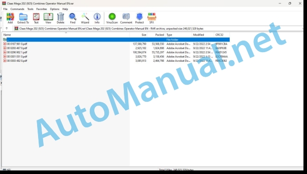
00 0187 961 0.pdf
00 0293 467 0.pdf
00 0296 902 1.pdf
00 0301 051 0.pdf
00 0303 482 0.pdf
00 0293 467 0.pdf:
02934670_de.pdf
Instructions for use with CLAAS-Bordinformator
Instructions
Besons on the beach
Kennzeichnung von Warn- und Gefahrenhinweisen
Bestimmungsgeme Verwendung
Functional elements of the Bordinformators
Functions of the Bordinformators on their Program Card
Bordinformator with added programmer card
Bordinformator in Betrieb nehmen
Zugschalter einstellen
Programmieren ohne Programmierkarte
Programmieren mit Programmierkarte
Distanzfaktor
Motoren-Nenndrehzahl
Einstelldaten
Reed contact service an der Vorlegewelle (V)
Induktivgeber an der hinteren Corn-Cracker-Walze (Feldhcksler)
Induktivgeber am Reinigungsgeblse (Mhdrescher)
Induktivgeber am Hauptgetriebe (Feldhcksler)
Induktivgeber Induktivgeber am Motorabtrieb (Feldhcksler)
Induktivgeber am Motorabtrieb (Mhdrescher)
02934670_en.pdf
Operator’s manual CLAAS fieldwork computer
Introduction
Table of contents
Important information
Identification of warning and danger signs
Intended use
Function elements of the fieldwork computer
Functions of the fieldwork computer without programming card
Fieldwork computer with programming card inserted
operating the fieldwork computer
Setting the pull switch
Programming without a programming card
Programming with programming card
Distance factor
Rated engine speed
Setting data
Reed switch on the intermediate drive shaft (V)
Magnetic pickup on the rear corn cracker roller (forage harvester)
Magnetic pickup on the cleaning fan (combine harvester)
Magnetic pickup on the main gearbox (drilling harvester)
Magnetic pickup on threshing drum or cutting cylinder
Magnetic ckup on toutput (drilling harvester)
Magnetic pickup on the engine output (combine harvester)
02934670_fr.pdf
Instructions for use CLAAS on-board informant
Introduction
Contents
Particularly important
Marking of warnings and dangers
Use in accordance with instructions
Function elements of the on-board informant
On-board informant functions without programming card
On-board informant with programming card in place
Switching on the on-board informant
Adjust barrel draw
Program without a programming card
Program with programming card
Distance factor
Rated engine speed
Setting parameters
Reed pressure switch on the intermediate train (V)
Inductive sensor on the rear roller of the Corn-Cracker (forage harvester)
Inductive sensor on cleaning fan (combine harvester)
Inductive sensor on the main gearbox (forage harvester)
Inductive sensor of the beater or blade holder
Inductive sensor on the motor output (forage harvester)
Inductive sensor on motor output (combine harvester)
02934670_it.pdf
CLAAS bordo computer user manual
Introduction
Important news
Warning and pericolo signal
Specific use
Functional elements of the computer on board
Computer functions on board according to the programming schedule
Computer on board with application programming schedule
Messa in use of the computer on board
Regulation of the switch on the strap
Programming according to the programming schedule
Programming with programming schedule
Fattore di distance
Rated engine speed
Regulatory data
Contact reed of the albero di rinvio (V)
Industrial transmission of the rear corn cracker wheel (trincia foraggi)
Industrial fan transmitter of the power fan (mietitrebbia)
Main transmission driver (trinciaforaggi)
Industrial transmission of the battery or the trinciatura drum
Engine power transmission (trimming)
Engine power transmission (lower speed)
02934670_ru.pdf
equipment
1.1.5 Qualified specialist workshop
1.1.6 Maintenance information
1.1.7 Warranty notes
1.1.8 Spare parts and technical questions
1.2 Intended use
1.2.1 Intended use
1.2.2 Reasonably foreseeable misuse
2 Safety
2.1 Identifying warnings
2.1.1 Hazard signs
2.1.2 Signal word
2.2 Safety rules
2.2.1 Meaning of Operator’s Manual
2.2.2 Observing safety decals and warnings
2.2.3 Optional equipment and spare parts
3 Product description
3.1 Overview and method of operation
3.1.1 How the PROFI CAM works
3.2 Identification plates and identification number
3.2.1 Position of identification plates
3.2.2 Explanation of PROFI CAM identification plate
3.3 Information on the product
3.3.1 CE marking
4 Operating and control elements
4.1 Camera system
4.1.1 Camera system monitor
4.2 Menu structure
4.2.1 Main menu
4.2.2
4.2.3
4.2.4
4.2.5
4.2.6
5 Technical specifications
5.1 PROFI CAM
5.1.1 Monitor
5.1.2 Camera
5.1.3 Switch box
5.1.4 Degree of protection against foreign bodies and water
6 Preparing the product
6.1 Shutting down and securing the machine
6.1.1 Switching off and securing the machine
6.2 Prior to operation
6.2.1 Carry out prior to operation
6.2.2 Installing the sun protection
6.2.3 Aligning the camera
6.2.4 Connecting the camera electrics
7 Operation
7.1 Monitor
7.1.1 Switching on the monitor
7.1.2 Calling up the menu
7.1.3 Setting a menu item
7.1.4 Setting the image orientation
7.1.5 Setting automatic screen darkening
7.1.6 Image mirroring
7.1.7 Setting the trigger view
7.1.8 Setting the follow-up time for trigger view
7.1.9 Setting the display mode
7.1.10 Activating/deactivating a display mode
8 Faults and remedies
8.1 Electrical and electronic system
8.1.1 Overview of problems on PROFI CAM camera system
8.1.2 Replacing the switch box fuse
9 Maintenance
9.1 Maintenance intervals
9.1.1 Every 10 operating hours or daily
9.2 Camera system
9.2.1 Checking the camera system for dirt
9.2.2 Cleaning the camera
9.2.3 Cleaning the switch box
9.2.4 Cleaning the monitor
10 Placing out of operation and disposal
10.1 General Information
10.1.1 Putting out of operation and disposal
11 Technical terms and abbreviations
11.1 Abbreviations
11.1.1 Units
11.1.2 Abbreviations
11.1.3 Technical terms
00 0303 482 0.pdf:
PROFI CAM 4
Table of contents
1 Introduction
1.1 Notes on the manual
1.1.1 Validity of manual
1.1.2 Information about this Operator’s Manual
1.1.3 Symbols and notes
1.1.4 Optional equipment
1.1.5 Qualified specialist workshop
1.1.6 Maintenance information
1.1.7 Notes on warranty
1.1.8 Spare parts and technical questions
1.2 Intended use
1.2.1 Intended use
1.2.2 Reasonably foreseeable misuse
2 Safety
2.1 Identifying warnings
2.1.1 Hazard signs
2.1.2 Signal word
2.2 Safety rules
2.2.1 Meaning of Operator’s Manual
2.2.2 Structural changes
2.2.3 Optional equipment and spare parts
2.2.4 Operation only following proper putting into operation
2.2.5 Technical status
2.2.6 Respecting technical limit values
Respecting technical limit values
2.2.7 Hazards when driving on roads and fields
3 Product description
3.1 Overview and method of operation
3.1.1 How the PROFI CAM works
3.2 Identification plates and identification number
3.2.1 Identification plates
3.3 Information on the product
3.3.1 CE marking
4 Operating and display elements
4.1 Camera system
4.1.1 Camera system monitor
4.1.2 CEBIS
4.2 Menu structure
4.2.1 Main menu
4.2.2
4.2.3
4.2.4
4.2.5
4.2.6
5 Technical specifications
5.1 PROFI CAM
5.1.1 Monitor
5.1.2 Camera
5.1.3 Switch box
6 Preparing the product
6.1 Switching off and securing the machine
6.1.1 Switching off and securing the machine
6.2 Prior to putting into operation
6.2.1 Carry out prior to operation
6.2.2 Installing the sun protection
6.2.3 Aligning the camera
7 Operation
7.1 Monitor
7.1.1 Switching on the monitor
7.1.2 Calling up the menu
7.1.3 Setting a menu item
7.1.4 Setting the image orientation
7.1.5 Setting automatic screen darkening
7.1.6 Image mirroring
7.1.7 Setting the trigger view
7.1.8 Setting the follow-up time for trigger view
7.1.9 Setting the display mode
7.1.10 Activating/deactivating a display mode
8 Faults and remedies
8.1 Electric and electronic system
8.1.1 Overview of problems on PROFI CAM camera system
9 Maintenance
9.1 Maintenance intervals
9.1.1 Every 10 operating hours or daily
9.2 Camera system
9.2.1 Checking the camera system for dirt
9.2.2 Cleaning the camera
9.2.3 Cleaning the switch box
9.2.4 Cleaning the monitor
10 Putting out of operation and disposal
10.1 General information
10.1.1 Putting out of operation and disposal
11 Technical terms and abbreviations
11.1 Abbreviations
11.1.1 Units
11.1.2 Abbreviations
11.1.3 Technical terms
John Deere Repair Technical Manual PDF
John Deere Repair Technical Manual PDF
John Deere Parts Catalog PDF
John Deere Harvesters 8500 and 8700 Parts Catalog CPCQ24910 Spanish
John Deere Repair Technical Manual PDF
John Deere Repair Technical Manual PDF
John Deere Repair Technical Manual PDF
John Deere 16, 18, 20 and 24HP Onan Engines Component Technical Manual CTM2 (19APR90)
John Deere Repair Technical Manual PDF
John Deere Repair Technical Manual PDF
John Deere POWERTECH E 4.5 and 6.8 L Diesel Engines TECHNICAL MANUAL 25JAN08
John Deere Repair Technical Manual PDF
John Deere Application List Component Technical Manual CTM106819 24AUG20

