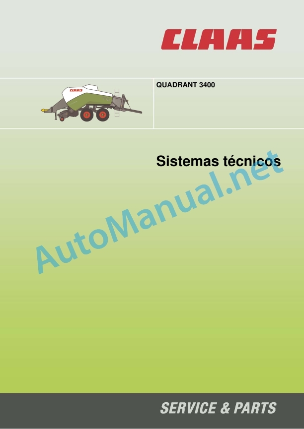
Claas Quadrant 3400 (740) Baler Technical System ES
$300.00
- Model: Quadrant 3400 (740) Baler
- Type Of Manual: Technical System
- Language: ES
- Format: PDF(s)
- Size: 6.4 MB
File List:
00 0291 432 0.pdf
00 0291 432 0.pdf:
QUADRANT 3400
CCN Explanation
CCN (CLAAS Component Number)
General indications
Regulations for electrical installation
Regulations for hydraulic installation
CCN (CLAAS Component Number)
Introduction
Validity of instructions
Machine summary
The Quadrant 3400 in summary
09 Hydraulic
0920 Valves
Raise/lower the Pick-up
Function Description
Hydraulic valve limiting the pressure of the filling chamber, up to machine no.
Hydraulic valve limiting the pressure of the filling chamber, from machine no.
Hydraulic valve controlling the neutral conveyor, up to machine no.
Function Description
Hydraulic valve controlling the neutral conveyor, from machine no.
Function Description
Cutting floor hydraulic valve, ROTO CUT, bale ramp, bale ejector
Hydraulic rotor clutch valve ON/OFF
Function Description
0980 Hydraulic connection diagram
Hydraulic connection diagram QUADRANT 3400 RC to machine no.
Hydraulic connection diagram QUADRANT 3400 RF to machine no.
QUADRANT 3400 RC hydraulic connection diagram from machine no.
QUADRANT 3400 RF hydraulic connection diagram from machine no.
Connection diagram of the hydraulic steering system
Function Description
Raise/lower the Pick-up
Function Description
Hydraulic connection diagram of the filling chamber, up to machine no.
Function Description
Filling chamber hydraulic connection diagram, starting from machine no.
Function Description
Hydraulic connection diagram for conveyor control, up to machine no.
Function Description
Hydraulic connection diagram for conveyor control, starting with machine no.
Function Description
Hydraulic connection diagram working hydraulic system – external oil supply
Table of measured values
Function description – connection to the tractor hydraulic system
Function Description – Hydraulic Operations System
Hydraulic connection diagram of the low pressure hydraulic system – rotor clutch
Function Description
10 Install. electrical/electronic
1010 Central electrical system
Module A020 - Claas Control Unit (CCU, 55 poles). Module A088 – Quadrant (additional module)
Module A020 - Claas Control Unit (CCU – 16 Plus, 70 poles)
1012 Modules / sensors
Module summary
Occupation of the A020 CCU / 55-pole modules – a)
Occupation of the A088 Quadrant modules (additional module) – a)
Occupation of the A020 CCU modules (16 plus) / 70 poles – b)
1080 Electronic connection diagram
Structure of the electrical installation documentation
Connection diagram
Connection List
CLAAS regulations:
01a Main voltage supply (CCU 55 poles)
Table of measured values
Function Descriptiion of the sockets
Connection List
01b Main voltage supply (CCU 16 plus, 70 po of measured values
Function Description
Occupation of the sockets
Connection List
06a CAN-Bus, module voltage supply (CCU 55 poles)
Table of measured values
Function Description
Occupation of the sockets
Connection List
06b CAN bus, module voltage supply (CCU 16 plus, 70 poles)
Table of measured values
Function Description
Occupation of the sockets
Connection List
07a ROTOCUT (CCU 55 poles)
Table of measured values
Machine with cutting bottom 854260.x
Function Description
Function description – sensor adjustment
Machine with cutting bottom 859940.X from nr. 74000221
Function Description
Function description – sensor adjustment
Occupation of the sockets
Connection List
07b ROTOCUT (CCU 16 plus, 70 poles)
Table of measured values
Machine with cutting bottom 859940.X from nr. 74000221
Function Description
Function description – sensor adjustment
Occupation of the sockets
Connection List
08a Feeding automation (CCU 55 poles)
Table of measured values
Function Description
Function description – sensor adjustment
Rotor automation process diagram
Occupation of the sockets
Connection List
08b Feeding automation (CCU 16 plus, 70 poles)
Table of measured values
Function Description
Function description – sensor adjustment
Rotor automation process diagram
Occupation of the sockets
Connection List
09a Carrier control, filling chamber (CCU 55 poles)
Table of measured values
Function Description
Filling chamber without modulation towards the piston position. Until machine no. 74000220
Carrier control table
Filling chamber with modulation towards the piston position. Starting with machine no. 74000221
Carrier control table
Function Description
Graphic: modulation of the filling chamber lid (Y245)
Occupation of the sockets
Connection List
09b Carrier control, filling chamber (CCU 16 plus, 70 poles)
Table of measured values
Function Description
Filling chamber without modulation towards the piston position. Until machine no. 74000220
Carrier control table
Filling chamber with modulation towards the piston position. Starting with machine no. 74000221
Carrier control table
Function Description
Graphic: modulation of the filling chamber lid (Y245)
Occupation of the sockets
Connection List
10th Regulation of baling pressure (CCU 55 poles)
Table of measured values
Function Description
Occupation of the sockets
Connection List
10b Baling pressure regulation (CCU 16 plus, 70 poles)
Table of measured values
Function Description
Occupation of the sockets
Connection List
11a Tying trip (CCU 55 poles)
Table of measured values
Function Description
Function description – sensor adjustment
Diagram of tied process and fault control
Occupation of the sockets
Connection List
11b Tying trigger (CCU 16 plus, 70 poles)
Table of measured values
Function Description
Function description – sensor adjustment
Diagram of tied process and fault control
Occupation of the sockets
Connection List
13a Eject bales (CCU 55 poles)
Table of measured values
Function Description
Occupation of the sockets
Connection List
13b Eject bales (CCU 16 plus, 70 poles)
Table of measured values
Function Description
Occupation of the sockets
Connection List
26a Machine control (CCU 55 poles)
Table of measured values
Function Description
Function description – sensor adjustment
Occupation of the sockets
Connection List
26b Machine control (CCU 16 plus, 70 poles)
Table of measured values
Function Description
Function description – sensor adjustment
Occupation of the sockets
Connection List
27a Service indicators (CCU 55 poles)
Table of measured values
Function Description
Function description – sensor adjustment
Occupation of the sockets
Connection List
27b Service indicators (CCU 16 plus, 70 poles)
Table of measured values
Function Description
Function description – sensor adjustment
Occupation of the sockets
Connection List
29a Central lubrication system (CCU 55 poles)
Table of measured values
Function Description
Occupation of the sockets
Connection List
29b Central lubrication system (CCU 16 plus, 70 poles)
Table of measured values
Function Description
Occupation of the sockets
Connection List
32nd Illumination
Function Description
Occupation of the sockets
Connection List
40a Additional sockets
Function Description
Occupation of the sockets
Connection List
21 Power set
2130 Carrier
Carrier – filling path in the baling chamber. Graphic 402348
Function Description
Carrier – feed the filling chamber. Graphic 402349
Function Description
Carrier – feed the filling chamber. Graphic 402350
Function Description
75 Central lubrication
7515 Lubrication/piping equipment
Central lubrication system (electric)
Central lubrication system pump
Function Description
Adjustment of the central lubrication system
Function Description
Location of components
Hydraulic
1000 Oil tank / oil filter
2000 Pump/motor
3000 Hydraulic Cylinders
4000 Choke/restrictor
5000 Pressure retainers
6000 Valves – mechanically actuated
7000 Valves – hydraulically actuated
9000 Measuring points / indicator instruments
Electrical installation
Component Grid
B Sensors
K Relays
M Motor (electric)
R Resistance
U External control switch
V Electronic part
and electromagnetic coils
Z Effective value switch
John Deere Repair Technical Manual PDF
John Deere Repair Technical Manual PDF
John Deere 18-Speed PST Repair Manual Component Technical Manual CTM168 10DEC07
New Holland Service Manual PDF
John Deere Repair Technical Manual PDF
John Deere Repair Technical Manual PDF
John Deere Application List Component Technical Manual CTM106819 24AUG20
John Deere Repair Technical Manual PDF
John Deere Repair Technical Manual PDF
John Deere Transmission Control Unit Component Technical Manual CTM157 15JUL05
John Deere Repair Technical Manual PDF
John Deere Diesel Engines PowerTech 4.5L and 6.8L – Motor Base Technical Manual 07MAY08 Portuguese
John Deere Repair Technical Manual PDF


