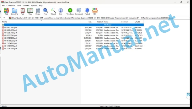
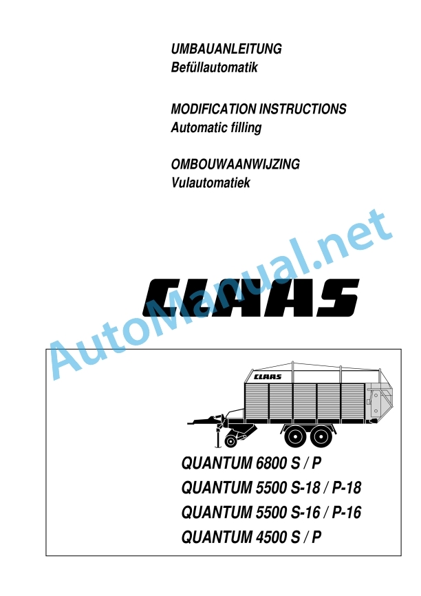
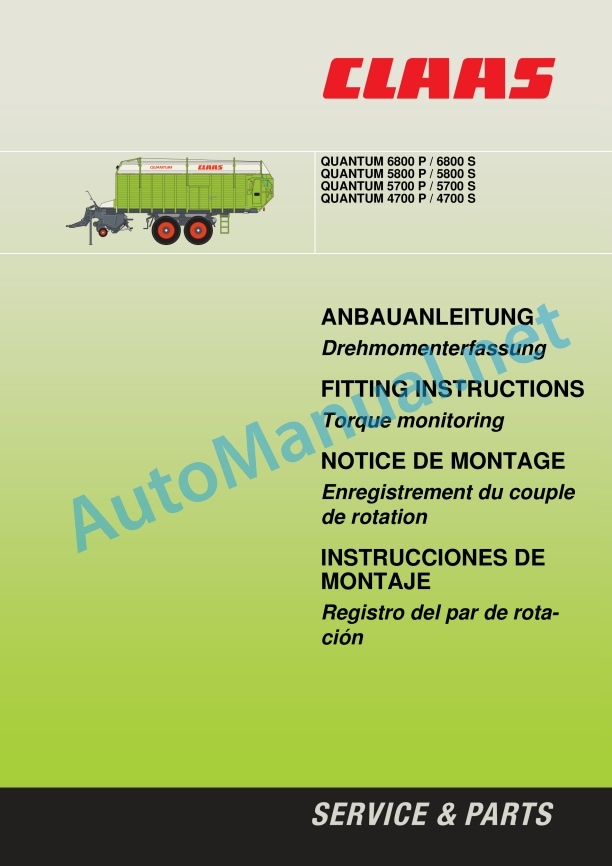
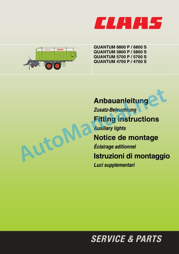
Claas Quantum 5500 S S16 S18 4500 S (614) Loader Wagons Assembly Instruction EN
$50.00
- Model: Quantum 5500 S S16 S18 4500 S (614) Loader Wagons
- Type Of Manual: Assembly Instruction
- Language: EN
- Format: PDF(s)
- Size: 29.4 MB
File List:
00 0290 143 2.pdf
00 0292 437 0.pdf
00 0296 716 0.pdf
00 0300 374 1.pdf
00 0973 902 3.pdf
00 0973 922 0.pdf
00 1316 421 1.pdf
00 1316 977 0.pdf
00 1325 214 4.pdf
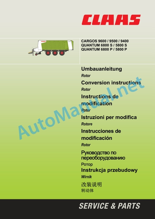
00 0296 716 0.pdf:
Headland lifting
1 Security
1.1 Particular attention should be paid to this
1.2 Intended use
1.3 General safety instructions
1.4 Warning symbols
1.4.1 Symbols Warnings
1 Safety
1.1 Of special importance
1.2 Intended use
1.3 General safety instructions
1.4 Safety decals
1 Security
1.1 Important
1.2 Conformité d’utilisation
1.3 General Security Consignments
1.4 Pictograms of avertissement
1 Safezza
1.1 Avvertenze importanti
1.2 Norme per il corretto impiego
1.3 General indications for safety
1.4 Decalcomanie with symbols of pericolo
1 security
1.1 A special observation
1.2 Utilización conforme to las normas previstas
1.3 General safety indicators
1.4 Rótulo adhesive de seguridad with symbol of advertencia
1 Общие ука C5B >A>1> >1@0B8BL 2=8<0=85
1.2 Introduction to the name
1.3 Instructions for the safety of the technique
1.4 Stickers with warning signs and symbols
00 0494 830 0
00 0494 830 0
00 0973 902 3.pdf:
Growing instructions
3. Metering roller
1 Introduction
Introduction
2 Contents
3 General information
Of particular note
Labeling of warnings and danger notices
Intended Use
Safety sticker with warning symbols
General safety instructions
4 scope of delivery
QUANTUM 6800 S / 5800 S / 5700 S / 4700 S – mounting kit 1315 072.0
QUANTUM 6800 S / 5800 S / 5700 S / 4700 S – mounting kit 1315 072.0
QUANTUM 6800 S / 5800 S / 5700 S / 4700 S – mounting kit 1315 072.0 – from machine number 614 0 2243 (straight version)
QUANTUM 5500 S / 4500 S – mounting kit 0973 621.1
QUANTUM 5500 S / 4500 S – mounting kit 0973 621.1
QUANTUM 5500 S / 4500 S – mounting kit 0973 621.1 – up to machine number 614 0 2242 (slanted version)ting kit 0973 621.1 – from machine number 614 0 2243 (straight version)
5 Dismantling sheet metal parts
Dismantle sheet metal parts
6 Assembly 3. Metering roller
Pre-assembly of metering roller up to machine number 614 0 2242 (angled version)
Pre-assembly of metering roller from machine number 614 0 2243 (straight version)
Assembly of metering roller up to machine number 614 0 2242 (angled version)
Make holes in the end plate (only for QUANTUM 5500 S / S-18 / S-16 and 4500 S).
Install the metering roller (1).
Assembly of metering roller from machine number 614 0 2243 (straight version)
Make holes in the end plate (only for QUANTUM 5800 S / 5700 S / 5500 S / 5500 S-18 / 5500 S-16 / 4700 S and 4500 S).
Install the metering roller (1).
Further assembly on all machines
Assembly of lubrication lines
Assembly of the metering roller drive
Mounting protective covers
Carry out a functional test
Check and observe before commissioning!
Fitting instructions
3rd shredder drum
1 Introduction
Introduction
2 Table of contents
3 General instructions
Of special importance
Identification of warnings and dangers
Designated use
Safety decals with warning symbols
General safety instructions
4 Package list
QUANTUM 6800 S / 5800 S / 5700 S / 4700 S – Mounting kit: 1315 072.0
QUANTUM 6800 S / 5800 S / 5700 S / 4700 S – Mounting kit: 1315 072.0
QUANTUM 6800 S / 5800 S / 5700 S / 4700 S – Mounting kit: 1315 072.0 – from machine No. 614 0 2243 (Straight version)
QUANTUM 6500 S / 4500 S – Mounting kit: 0973 621.1
QUANTUM 6500 S / 4500 S – Mounting kit: 0973 621.1
QUANTUM 6500 S / 4500 S – Mounting kit: 0973 621.1 – up to machine No. 614 0 2242 (Inclined version)
QUANTUM 6500 S / 4500 S – Mounting kit: 0973 621.1 – from machine No. 614 0 2243 (Straight version)
5 Removing sheet metal parts
Removing sheet metal parts
6 Fitting the 3rd shredder drum
Shredder drum assembly to machine no. 614 0 2242 (inclined version)
Shredder drum assembly from machine no. 614 0 2243 (straight version)
Shredder drum assembly to machine no. 614 0 2242 (inclined version)
Drill holes on end plate (QUANTUM 5500 S / S-18 / S-16 and 4500 S).
Mount shredder drum (1)
Shredder drum assembly from machine no. 614 0 2243 (straight version)
Drill holes in the closing plate (only on QUANTUM 5800 S / 5700 S / 5500 S / 5500 S-18 / 5500 S-16 / 4700 S and 4500 S).
Mount shredder drum (1)
Continuing assembly for all machines
Installing lubrication lines
Installing shredder drum drive
Installing guard covers
Functional check
Check and observe the following before putting into operation
Manual de assembly
3ème tambour doseur
1 Introduction
Introduction
2 Table des matières
3 general councils
Important
Identification of the prescriptions concerning the avertissements and the dangers
Utilization conforme à l’usage prévu
Etiquette de security with pictograms of danger
General Security Consignments
4 pieces fournies
QUANTUM 6800 S / 5800 S / 5700 S / 4700 S – Ably kit: 1315 072.0
QUANTUM 6800 S / 5800 S / 5700 S 00 S – Assembly kit: 1315 072.0
QUANTUM 6800 S / 5800 S / 5700 S / 4700 S – Assembly kit: 1315 072.0 – machine number N˚ 614 0 2243 (Présentation droite)
QUANTUM 5500 S / 4500 S – Assembly kit: 0973 621.1
QUANTUM 5500 S / 4500 S – Assembly kit: 0973 621.1
QUANTUM 5500 S / 4500 S – Jeu d’assemblage: 0973 621.1 – from the machine N˚ 614 0 2242 (Présentation inclinée)
QUANTUM 5500 S / 4500 S – Jeu d’assemblage: 0973 621.1 – from the machine N˚ 614 0 2243 (Présentation droite)
5 disassembly parties en tôle
Démonter les parties en tôle
6 Montage du 3ème tambour doseur
Prémontage du tambour doseur jusqu’à la machine N˚ 614 0 2242 (présentation inclinée)
Prémontage du tambour doseur jusqu’à la machine N˚ 614 0 2243 (présentation droite)
Montage du tambour doseur jusqu’à la machine N˚ 614 0 2242 (presentation inclinée)
Effect of the results on the level of fermentation (pour QUANTUM 5500 S / S-18 / S-16 and 4500 S le tambour doseur (1)
Assembly of the drum doseur to par 0 2243 (presentation three)
Effect of the results on the level of fermentation (for QUANTUM 5800 S / 5700 S / 5500 S / 5500 S-18 / 5500 S-16 / 4700 S and 4500 S unique).
Monter le tambour doseur (1)
Other montages on all machines
Assembly of the conduites de graissage
Montage de l’entraînement du tambour doseur
Assembly of the fermetures de protection
Effectuer un control des functions
A control and surveillance before the mise en service!
Aanbouwhandleiding
3. Doseerwals
1 injury
Insuffering
2 Inhoudsoopgave
3 Algemene aanwijzingen
What you can do with my letten
Aanduiding van waarschuwingen en gevaren
Use as a result of besting
Veiligheidsstickers with warning symbols
Algemene veiligheidsvorschrifts
4 Leveringsomvang
QUANTUM 6800 S / 5800 S / 5700 S / 4700 S – Aanbouwset: 1315 072.0
QUANTUM 6800 S / 5800 S / 5700 S / 4700 S – Aanbouwset: 1315 072.0
QUANTUM 6800 S / 5800 S / 5700 S / 00 S – Aanbouwset: 1315 072.0 – vanaf machine no. 614 0 2243 (right uitvoering)
QUANUM 5500 S / 4500 S – Address: 0973 621.1
QUANTUM 5500 S / 4500 S – Address: 0973 621.1
QUANTUM 5500 S / 4500 S – Address: 0973 621.1 – dead machine no. 614 0 2242 (shuine uitvoering)
QUANTUM 5500 S / 4500 S – Aanbouwset: 0973 621.1 – vanaf machine no. 614 0 2243 (right uitvoering)
5 dismantling plaatdelen
Dismantle plates
6 Assembly 3de doseerwals
Pre-assembly doseerwals dead machine no. 614 0 2242 (shuine uitvoering)
Pre-assembly of the box according to the machine number. 614 0 2243 (right uitvoering)
Assembly doseerwals dead machine no. 614 0 2242 (shuine uitvoering)
Boorgaten aan de afsluitplaat maken (alleen beij QUANTUM 5500 S / S-18 / S-16 en 4500 S).
Mount canned whale (1).
Assembly doseerwals vanaf machine no. 614 0 2243 (right uitvoering)
Boorgaten aan de afsluitplaat maken (grandchildren of the QUANTUM 5800 S / 5700 S / 5500 S / 5500 S-18 / 5500 S-16 / 4700 S and 4500 S).
Mount canned whale (1).
Verdere assembly for all machines
Assembly smeerleidingen
Assembly doseerwalsaandrijving
Assembly beschermafdekkingen
Functiecontrole uitvoeren
For the engineering control, be careful!
00 1316 421 1.pdf:
Anbauanleitung
Drehmomenterfassung
1 Instructions
Instructions
2 Inhalt
3 Allgemeine Hinweise
Besons on the beach
Kennzeichnung von Warn- und Gefahrenhinweisen
Bestimmungsgemäße Verwendung
Sicherheitaveckleber mit Warnbildzeichen
Allgemeine Sicherheitshinweise
4 Lieferumfang
Lieferumfang für Anbausatz Drehmomenterfassung
Contact: 00 1316 415 0
5 Anbau Drehmomentstütze
QUANTUM 6800P, 6800S, 5800P, 5800S:
Schutzabdeckung abbauen
Bolzen demontieren
Messwertgeber mountieren
Messwertgeber anschließen
Protective cover
QUANTUM 5700 P, 5700 S, 4700 P, 4700 S:
Schutzabdeckung abbauen
Demonstrated Stütze
Stütze mountieren
Messwertgeber mountieren
rtgeber anschließen
Protective cover
You can open the doors and the beaches!
Fittructions
Torque monitoring
1 Introduction
Introduction
2 Contents
3 General instructions
Of special importance
Identification of warnings and dangers
Designated use
Safety decals with warning symbols
General safety instructions
4 Package list
Package list for installation kit, torque monitoring
Installation kit: 00 1316 415 0
5 Fitting the torque support
QUANTUM 6800P, 6800S, 5800P, 5800S:
Dismantling safety covers
Removing the locking pin
Fitting the measuring transducer
Connecting the measuring transducer
Fitting the safety covers
QUANTUM 5700 P, 5700 S, 4700 P, 4700 S:
Dismantling safety covers
Removing the support
Fitting the support
Fitting the measuring transducer
Connecting the measuring transducer
Fitting the safety covers
Check and observe prior to operation!
Installation instuctions
Torque recording
1 Introduction
Introduction
2 Table of contents
3 General tips
Important
Identification of warning and hazard requirements
Use as intended
Safety label with danger pictogram
General safety instructions
4 pieces supplied
Parts supplied for the torque recorder mounting kit
Assembly clearance: 00 1316 415 0
5 Rotation torque support assembly
QUANTUM 6800 P, 6800 S, 5800 P, 5800 S:
Dismantling the protective covers
Disassembly of the bolt
Mounting the measured value sensor
Connecting the measured value sensor
Fitting the protective covers
QUANTUM 5700 P, 5700 S, 4700 P, 4700 S:
Dismantling the protective covers
Dismantling of the support
Mounting the support
Mounting the measured value sensor
Connecting the measured value sensor
Fitting the protective covers
To be checked and respected before commissioning!
Assembly instructions
Rotation Registry
1 Introduction
Introduction
3 General information
To observe in special
Identification of warning and warning signs
Use in accordance with prescribed standards
Safety sticker with warning symbol
General safety information
4 Suministro Set
Set of suministro for the game to mount the recorder by rotation
Mounting game: 00 1316 415 0
5 Mounting of the rotating support
QUANTUM 6800P, 6800S, 5800P, 5800S:
Remove the protective cover
Remove the perno
Switch on the transmitter
Connect the transmitter
Install the protective cover
QUANTUM 5700 P, 5700 S, 4700 P, 4700 S:
Remove the protective cover
Remove the holder
Montar el soporte
Switch on the transmitter
Connect the transmitter
Install the protective cover
¡Comprobar and observe before the door is on the move!
00 1316 977 0.pdf:
Anbauanleitung
Zusatz-Beleuchtung
1 Instructions
Instructions
2 Inhalt
3 Allgemein Hinweise
Besons on the beach
Kennzeichnung von Warn- und Gefahrenhinweisen
Bestimmungsgemäße Verweng
Sicherheitaveckleber mit Warnbildzeichen
Allgemeine Sicherheitshinweise
Fitting instructions
Auxiliary lights
1 Introduction
Introduction
2 Contents
3 General instructions
Of special importance
Identification of warnings and dangers
Designated use
Safety decals with warning symbols
General safety instructions
Installation instructions
Additional lighting
1 Introduction
Introduction
2 Indexes
3 General tips
Important
Identification of warning and hazard requirements
Use as intended
Safety label with danger pictogram
General safety instructions
Mountain structure
Luci extra
1 Introduction
Introduction
3 General information
Important warnings
Symbols concern warnings and warnings of pericolo
Norm per il corretto impiego
Decal with pericolo symbol
General safety informati
Lieferumfang
Package list
Parts supplied
Complete furnishings
Kit: 00 1316 795 0
Arbeitsfolge
Procedure
Sequence of work
Procedure
John Deere Repair Technical Manual PDF
John Deere Parts Catalog PDF
John Deere Tractors 6300, 6500, and 6600 Parts Catalog CQ26564 (29SET05) Portuguese
John Deere Repair Technical Manual PDF
John Deere Transmission Control Unit Component Technical Manual CTM157 15JUL05
John Deere Repair Technical Manual PDF
John Deere POWERTECH E 4.5 and 6.8 L Diesel Engines TECHNICAL MANUAL 25JAN08
John Deere Repair Technical Manual PDF
John Deere Repair Technical Manual PDF
John Deere DF Series 150 and 250 Transmissions (ANALOG) Component Technical Manual CTM147 05JUN98
John Deere Repair Technical Manual PDF
John Deere Application List Component Technical Manual CTM106819 24AUG20
New Holland Service Manual PDF
John Deere Parts Catalog PDF
John Deere Harvesters 8500 and 8700 Parts Catalog CPCQ24910 Spanish

