Claas Scorpion 7035 (K23) Telehandlers Operator Manual EN
$50.00
- Model: Scorpion 7035 (K23) Telehandlers
- Type Of Manual: Operator Manual
- Language: EN
- Format: PDF(s)
- Size: 62.7 MB
File List:
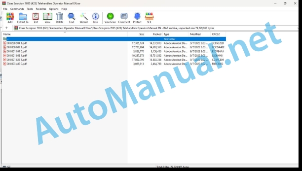
00 0298 904 1.pdf
00 0300 087 1.pdf
00 0301 051 0.pdf
00 0301 803 1.pdf
00 0301 828 1.pdf
00 0303 482 0.pdf
00 0298 904 1.pdf:
Operator’s Manual
Table of contents
EC Declaration of Conformity
EC Declaration of Conformity
EC Declaration of Conformity
EC Declaration of Conformity
1 Foreword
1.1 Operator’s Manual
Important information on the operating personnel
Important information on this Operator’s Manual
Explanation of symbols and abbreviations
1.2 Warranty and liability
Information on maintenance, repairs and spare parts
2 Safety
2.1 Safety symbols and signal words
Explanation
2.2 Conduct and safety instructions
Prerequisites for operation
2.3 Qualification of operating and maintenance personnel
Owner’s duties
Required knowledge of operator
Preparatory measures for the operator
2.4 Operation
Preparatory measures
Job site
Danger ng passengers
Mechanical integrity
Starting the engine of the machine
Machine operation
Machine travel on public roads/sites
Stopping the engine of the machine
Stopping and securing the machine
2.5 Lifting gear applications
Requirements
Fastening, guiding and removing loads
Lifting gear applications
2.6 Trailer operation
Trailer operation
2.7 Attachment operation
Attachments
Operation
Removing and fitting attachments
2.8 Towing, loading and transporting
Crane-lifting
Transport
2.9 Maintenance
Maintenance
Personal safety measures
Preparatory measures
Measures for performing maintenance
Modifications and spare parts
Protective structures
2.10 Measures for avoiding risks
Hydraulic and compressed-air system
Electrical system
Safety instructions regarding internal combustion engines
Bleeding the fuel system and refuelling
Handling oil, grease and other substances
Fire hazard
Working near electric supply lines
Working near non-electric supply lines
Behaviour during thunderstorm
Cleaning
3 Introduction
3.1 Machine overview
Models and trade names (overview)
3.2 Brief description of machine
Main components of machine
Hydrostatic drive
Operating hydraulics and 4 wheel steering
Cooling system
3.3 Information and regulations on use
General information on the machine
Safe machine operation
Designated use
Improper use
Permissible temperature range during normal operation
Driving licence
Identification
Machine inspections
Documents
On-board equipment
Warning identification of machine on public roads (option)
Fields of application and use of attachments
3.4 Labels
Labels on left side of machine (overview)
Labels on right side of machine (overview)
Labels at front of machine (overview)
Labels at rear of machine (overview)
Type labels
Warning labels
Information labels
4 Putting into operation
4.1 Cabin/control stand
Important information on the cabin
Safety instructions regarding accessing and leaving the cabin
Locking/unlocking the door
Opening/closing the rear window
Rear window emergency exit
Emergency exit – emergency hammer (option)
Safety instruction – side window (right)
Field of vision during road travel
Field of vision during work operation
Mirror adjustment
Camera (option)
Rear window heating (option), mirror heating (option)
Seat adjustment
Air-suspension seat (option)
Seat belt (lap belt)
Battery master switch
Fire extinguisher (option)
Key-based immobilizer (option)
Hydraulic oil and coolant preheating (option)
Fuel preheater (option)
Storage bins (option)
4.2 Overview of control elements
Description of control elements
Inside the cabin
Instrument panel with control elements
4.3 Indicator lights and warning lights (overview)
Indicator lights and warning lights on the indicating instrument
Indicator lights – instrument panel on the right
Indicator lights – steering-mode switch
Indicator lights and warning lights – lower section of instrument panel
Indicator light check
Information display on the indicating instrument
Acoustic warnings
Indicators
4.4 Preparatory work
Important information before putting the machine into operation
Requirements and information for the operating personnel
Running-in period
Check lists
Instructions for machine travel on public roads
Preparing machine travel on public roads
Locking the control lever (joystick)
Functional check of brakes, steering system and lights
4.5 Starting and stopping the engine
Preparing to start the engine
Starting the engine
Jump-starting the engine
Avoiding low-load engine operation
Stopping the engine
5 Operation
5.1 Steering system
Steering column height and angle adjustment
Checking the steering system
Synchronizing the steering system
Synchronizing the steering system in manual mode
Front axle steering
4 wheel steering
Diagonal steering (crab steering)
5.2 Accelerator actuation
Accelerator pedal
Manual throttle (option)
5.3 Brakes
Brake/inching pedal (service brake)
Parking brake
5.4 Travel operation
Performing machine travel
Overview of speed ranges
Changing speed range
Selecting the travel direction
Reversing operation (changing travel direction)
Neutral position, stopping the machine
Parking the machine
Low-speed control (option)
5.5 Differential lock
Important information on the differential lock
5.6 Lights/signalling system
Parking lights/low beam
High beam/headlight flasher
Working lights (standard/option)
Interior light
Turn indicators
Hazard warning system
Rotating beacon (option)
Backup warning system (option)
5.7 Wiper/wash system
Washer system operation
Washer system reservoir
5.8 Heating, ventilation and air conditioning system
Heating and ventilation
Air conditioning (option)
5.9 Operating hydraulics
Overload control
Telescopic boom operation
“Smart Handling” overload control
Overview of hydraulic control circuits
Hydraulic oil volume setting (option)
3rd control circuit
Changing over the 3rd control circuit to plug couplings B with the changeover valve (option)
Continuous operation of 3rd control circuit (option)
Releasing the pressure on the quick couplers on the quickhitch
5.10 Attachments
Checking the lock bores of the atment
stalling an attachment on a quickhitch with a hydraulic lock
Installing an attachment on a quickhitch with a mechanical lock
Removing an attachment from the quickhitch with mechanical locking
Removing an attachment from the quickhitch with hydraulic locking
Standard bucket
Multipurpose bucket (option)
Pallet forks
Fitting attachments from other manufacturers (option) for model 415-01_6030
Fitting attachments from other manufacturers (option) for model 415-01_6035
Fitting attachments from other manufacturers (option) for model 415-03
Fitting attachments from other manufacturers (option) for model 415-05
5.11 Work operation
“Hose burst valve” safety feature
Machine travel on public roads with a bucket
Safety instructions regarding work with a bucket
Transporting with a full bucket
Load stabilizer for loader unit (option)
Working with a standard bucket
Working with the multipurpose bucket
Working with pallet forks
Working with a crane jib (option)
Bucket repositioning (option under preparation)
Tilt ram lock (option)
Front socket (option)
5.12 Emergency lowering
Emergency lowering of loader unit in case of diesel engine breakdown
5.13 Options
Automatic trailer coupling (option)
Ball trailer coupling ø 80 mm (option)
Autohitch coupling (option)
Tipping trailer operation (option)
Compressed-air braking system of trailer (option)
Hydraulic trailer brake (option)
Reversing fan (option)
PROFI CAM/PROFI CAM PLUS (option)
Before putting the PROFI CAM / PROFI CAM PLUS into operation
Operation of the PROFI CAM/PROFI CAM PLUS
5.14 Putting out of operation/back into operation
Putting the machine out of operation for longer time
Preserving the diesel engine
5.15 Permanently putting out of operation
Information on decommissioning
Preparing disposal
Disposal
6 Transprt
6.1 Towingthe machine
Information on towing
Disabling the variable displacement pump
Rear towing gear
Front towing gear
Towing the machine
Once towing is over
6.2 Loading the machine
Loading the machine on a transport vehicle
Crane-lifting
6.3 Transporting the machine
Safety instructions regarding transport
Tying down the machine
7 Maintenance
7.1 Information on maintenance
Responsibilities and prerequisites
Important safety instructions regarding maintenance
Safety prop for telescopic boom
7.2 Maintenance overview
Maintenance plan
Maintenance label
Explanation of symbols on the maintenance label
7.3 Fluids and lubricants
Overview of lubricants
Diesel fuel specification
Important information on operation with biodegradable oils
7.4 Maintenance accesses
Engine cover lock
Engine vat
Maintenance access at the rear of the machine
Access to machine fuses
7.5 Cleaning and maintenance
Important information on cleaning and maintenance
Cleaning inside the cabin
Cleaning the exterior of the machine
Cleaning the engine and the engine compartment
Checking threaded fittings
Checking pivots and hinges
7.6 Lubrication work
Preparing lubrication
Lubricating the rear axle oscillation-type bearing
Lubricating the planetary drive bearing (front and rear axles)
Lubricating the door
Lubricating the telescopic boom
Checking the slide plates
Spraying oil onto the slide plates after a salt application (with a spray lance)
Central lubrication system (option)
Lubricating with the central lubrication system (option)
Filling the central lubrication system (option)
7.7 Fuel system
Important safety instructions for refuelling
Stationary fuel pumps
Refuelling
Checking/cleaning the fuel prefilter
Bleeding the fuel system
Replacing the fuel filter
7.8 Engine lubrication system
Important safety instructions regarding the engine lube oil system
Checking the engine oil level
Adding engine oil
Changing engine oil
Replacing the engine oil filter
7.9 Cooling system
Safety instructions regarding the cooling system
Information on inspection and cleaning work on the cooling system
Checking the coolant level
Adding coolant
Draining/replacing coolant
Cleaning the radiator
Cleaning the radiator with the reversing fan (option)
7.10 Air filter
Important information on cleaning the air filter
Cleaning the dust valve
Replacing the filter cartridge
7.11 V-belt/toothed belt
Checking/retightening the V-belt
7.12 Hydraulic system
Important information on the hydraulic system
Monitoring the hydraulic oil filter
Hydraulic oil level monitoring (option)
Checking the hydraulic oil level
Adding hydraulic oil
Checking the hydraulic system for leaks
Checking the condition and age of hydraulic hoses
7.13 Electrical system
Qualification of maintenance personnel
Safety instructions regarding the battery
Checking/replacing the battery
Inspections and maintenance on the electrical system at regular intervals
Checking the alternator
Checking/replacing relays and fuses on the board
Main fuse box with switching relays
7.14 Heating, ventilation and air conditioning system
Important information on cabin ventilation
Cleaning/replacing the cabin ventilation filter
Air conditioning (option)
Important safety instructions regarding the air conditioning system
Filling up the air conditioning system
Visual check of the air conditioning system
Cleaning the heat exchanger (condenser)
7.15 Washer system
Washer system reservoir
7.16 Axles/travelling drive
Maintenance on axles/drive
7.17 Braking system
Important safety instructions regarding the braking system
Checking/adding brake fluid
Compressed-air braking system (option)
7.18 Tyres
Important information on the tyres
Tyre check
Removing the wheels
Mounting the wheels
7.19 Maintenance of attachments
7.20 Maintenance of options
Automatic trailer coupling (option)
Ball trailer coupling ø 80 mm (option)
Autohitch trailer coupling (option)
Maintenance of the PROFI CAM/PROFI CAM PLUS
7.21 Exhaust gas treatment
7.22 Machine preservation
Important information on anticorrosion protection (option)
Measures for maintaining anticorrosive protection
Cleaning
Applying the protective anticorrosion coating
Treatment of oxidized surfaces
8 Malfunctions
8.1 Diesel engine malfunctions
8.2 Drive malfunctions
8.3 Malfunctions of the hydraulic system
8.4 Malfunctions of the electrical system
Digital display of error codes
Overview of frae electronics erro codes
Overview error codes of diesel engine electronics
Overview of cabin electronics error codes
Drive electronics error codes (overview)
Overview of joystick error codes
Overview of overload control error codes
Overview of steering electronics error codes
Overview of additional frame electronics error codes
Error codes in overload control display
8.5 Malfunctions in the air conditioning system (option)
9 Technical data
9.1 Model and trade names
9.2 Engine
Engine exhaust-emission level 3b (applies to all EU member states)
Engine exhaust-emission level 3a (applies to non-EU member states)
Oil/water fan
9.3 Travelling drive/axles
Variable displacement pump
Variable displacement motor
Front axle
Rear axle
9.4 Brakes
Service brake
Parking brake
9.5 Tyres
Tyres for models 415-01_6030/415-01_6035
Tyres for model 415-03/415-05
9.6 Steering system
9.7 Operating hydraulics
Hydraulic pump
Hydraulic ram protection
Lift, tilt and push-out rams: velocity
Electro-hydraulic pilot control
Usable consumer pressure at additional control circuit (option)
9.8 Electrical system
Fuse assignment
Main fuse box with relays
Switching relay assignment
Electrical components
PROFI CAM/PROFI CAM PLUS (option)
9.9 Tightening torques
General tightening torques
Specific tightening torques
9.10 Coolant
9.11 Noise emissions
9.12 Vibration
9.13 Weight
9.14 Payload/lift capacity/stability
Trailer weight/drawbar load
Breakout force
Bucket payload
Load diagrams
9.15 Dimensions
Dimensions with bucket (part I)
Dimensions with bucket (part II)
Dimensions with pallet forks
00 0301 051 0.pdf:
PROFI CAM 3
Table of contents
1 Introduction
1.1 Notes on the manual
1.1.1 Validity of manual
1.1.2 Information about this Operator’s Manual
1.1.3 Symbols and notes
1.1.4 Optional equipment
1.1.5 Qualified specialist workshop
1.1.6 Maintenance information
1.1.7 Warranty notes
1.1.8 Spare parts and technical questions
1.2 Intended use
1.2.1 Intended use
1.2.2 Reasonably foreseeable misuse
2 Safety
2.1 Identifying warnings
2.1.1 Hazard signs
2.1.2 Signal word
2.2 Safety rules
2.2.1 Meaning of Operator’s Manual
2.2.2 Observing safety decals and warnings
2.2.3 Optional equipment and spare parts
3 Product description
3.1 Overview and method of operation
3.1.1 How the PROFI CAM works
3.2 Identification plates and identification number
3.2.1 Position of identification plates
3.2.2 Explanation of PROFI CAM identification plate
3.3 Information on the product
3.3.1 CE marking
4 Operating and control elements
4.1 Camera system
4.1.1 Camera system monitor
4.2 Menu structure
4.2.1 Main menu
4.2.2
4.2.3
4.2.4
4.2.5
4.2.6
5 Technical specifications
5.1 PROFI CAM
5.1.1 Monitor
5.1.2 Camera
5.1.3 Switch box
5.1.4 Degree of protection against foreign bodies and water
6 Preparing the product
6.1 Shutting down and securing the machine
6.1.1 Switching off and securing the machine
6.2 Prior to operation
6.2.1 Carry out prior to operation
6.2.2 Installing the sun protection
6.2.3 Aligning the camera
6.2.4 Connecting the camera electrics
7 Operation
7.1 Monitor
7.1.1 Switching on the monitor
7.1.2 Calling up the menu
7.1.3 Setting a menu item
7.1.4 Setting the image orientation
7.1.5 Setting automatic screen darkening
7.1.6 Image mirroring
7.1.7 Setting the trigger view
7.1.8 Setting the follow-up time for trigger view
7.1.9 Setting the display mode
7.1.10 Activating/deactivating a display mode
8 Faults and remedies
8.1 Electrical and electronic system
8.1.1 Overview of problems on PROFI CAM camera system
8.1.2 Replacing the switch box fuse
9 Maintenance
9.1 Maintenance intervals
9.1.1 Every 10 operating hours or daily
9.2 Camera system
9.2.1 Checking the camera system for dirt
9.2.2 Cleaning the camera
9.2.3 Cleaning the switch box
9.2.4 Cleaning the monitor
10 Placing out of operation and disposal
10.1 General Information
10.1.1 Putting out of operation and disposal
11 Technical terms and abbreviations
11.1 Abbreviations
11.1.1 Units
11.1.2 Abbreviations
11.1.3 Technical terms
00 0301 803 1.pdf:
Operator’s Manual
Table of contents
EC Declaration of Conformity
Declaration of manufacturer
1 Preface
1.1 Operator’s Manual
1.2 Warranty and liability
2 Safety
2.1 Safety symbols and signal words
2.2 Conduct and safety instructions
2.3 Qualification of operating and maintenance personn 2.4 Operation
2.5 Lifting gear applications
2.6 Trailer operation
2.7 Attachment opera
2.8 Towing, loading and transporting
2.9 Maintenance
2.10 Measures for avoiding risks
3 Introduction
3.1 Machine overview
3.2 Brief description of machine
3.3 Information and regulations on use
3.4 Labels
4 Putting into operation
4.1 Cabin/control stand
4.2 Overview of control elements
4.3 Indicator lights and warning lights (overview)
4.4 Preparatory work
4.5 Starting and stopping the engine
5 Operation
5.1 Steering system
5.2 Accelerator actuation
5.3 Brake
5.4 Travel operation
5.5 Differential lock
5.6 Lights/signalling system
5.7 Wiper/wash system
5.8 Heating, ventilation and air conditioning system
5.9 Work hydraulics
5.10 Attachments
5.11 Work operation
5.12 Emergency lowering
5.13 Options
5.14 Decommissioning andrecommissioning
5.15 Final decommissioning
6 Transport
6.1 Towing the machine
6.2 Loading the machine
6.3 Transporting the machine
7 Maintenance
7.1 Information on maintenance
7.2 Maintenance overview
7.3 Fluids and lubricants
7.4 Maintenance accesses
7.5 Cleaning and maintenance
7.6 Lubrication work
7.7 Fuel system
7.8 Engine lubrication system
7.9 Cooling system
7.10 Air filter
7.11 V-belt/toothed belt
7.12 Hydraulic system
7.13 Electrical system
7.14 Heating, ventilation and air conditioning system
7.15 Washer system
7.16 Axles/travelling drive
7.17 Braking system
7.18 Tires
7.19 Maintenance of attachments
7.20 Maintenance of options
7.21 Exhaustgas treatment
7.22 Machine preservation
8 Malfunctions
8.1 Diesel engine malfunctions
8.2 Malfunctions of the traveling drive
8.3 Malfunctions of the hydraulic system
8.4 Malfunctions of the electrical system
8.5 Malfunctions in the air conditioning system (option)
9 Technical data
9.1 Model and trade names
9.2 Engine
9.3 Travelling drive/axles
9.4 Brakes
9.5 Tyres
9.6 Steering system
9.7 Work hydraulics
9.8 Electrical system
9.9 Tightening torques
9.10 Coolant
9.11 Noise emissions
9.12 Vibration
9.13 Weight
9.14 Payload/lift capacity/stability
9.15 Dimensions
00 0301 828 1.pdf:
Operator’s Manual
Table of contents
EC Declaration of Conformity
1 Preface
1.1 Operator’s Manual
1.2 Warranty and liability
2 Safety
2.1 Safety symbols and signal words
2.2 Conduct and safety instructions
2.3 Qualification of operating and maintenance personnel
2.4 Operation
2.5 Lifting gear applications
2.6 Trailer operation
2.7 Attachment operation
2.8 Towing, loading and transporting
2.9 Maintenance
2.10 Measures for avoiding risks
3 Introduction
3.1 Machine overview
3.2 Brief description of machine
3.3 Information and regulations on use
3.4 Labels
4 Putting into opern
4.1 Cabin/control stand
4.2 Overview of control elements
4.2 Indicator lights and warning li (overview)
4.3 Preparatory work
4.4 Starting and stopping the engine
5 Operation
5.1 Steering system
5.2 Accelerator actuation
5.3 Brake
5.4 Travel operation
5.5 Differential lock
5.6 Lights/signalling system
5.7 Wiper/wash system
5.8 Heating, ventilation and air conditioning system
5.9 Work hydraulics
5.10 Attachments
5.11 Work operation
5.12 Emergency lowering
5.13 Options
5.14 Decommissioning and putting the machine back into operation
5.15 Permanently putting out of operation
6 Transport
6.1 Towing the machine
6.2 Loading the machine
6.3 Transporting the machine
7 Maintenance
7.1 Information on maintenance
7.2 Maintenance overview
7.3 Fluids and lubricants
7.4 Maintenance accesses
7.5 Cleaning and maintenance
7.6 Lubrication work
7.7 Fuel system
7.8 Engine lubrication system
7.9 Cooling system
7.10 Air filter
7.11 V-belt/toothed belt
7.12 Hydraulic system
7.13 Electrical system
7.14 Heating, ventilation and air conditioning system
7.15 Washer system
7.16 Axles/travelling drive
7.17 Braking system
7.18 Tyres
7.19 Maintenance of attachments
7.20 Maintenance of options
7.21 Exhaustgas treatment
7.22 Machine preservation
8 Malfunctions
8.1 Diesel engine malfunctions
8.2 Malfunctions of the traveling drive
8.3 Malfunctions of the hydraulic system
8.4 Malfunctions of the electrical system
8.5 Malfunctions in the air conditioning system (option)
9 Technical data
9.1 Model and trade names
9.2 Engine
9.3 Travelling drive/axles
9.4 Brakes
9.5 Tyres
9.6 Steering system
9.7 Work hydraulics
9.8 Electrical system
9.9 Tightening torques
9.10 Coolant
9.11 Noise emissions
9.12 Vibration
9.13 Weight
9.14 Payload/lift capacity/stability
9.15 Dimensions
00 0303 482 0.pdf:
PROFI CAM 4
Table of contents
1 Introduction
1.1 Notes on the manual
1.1.1 Validity of manual
1.1.2 Information about this Operator’s Manual
1.1.3 Symbols and notes
1.1.4 Optional equipment
1.1.5 Qualified specialist workshop
1.1.6 Maintenance information
1.1.7 Notes on warranty
1.1.8 Spare parts and technical questions
1.2 Intended use
1.2.1 Intended use
1.2.2 Reasonably foreseeable misuse
2 Safety
2.1 Identifying warnings
2.1.1 Hazard signs
2.1.2 Signal word
2.2 Safety rules
2.2.1 Meaning of Operator’s Manual
2.2.2 Structural changes
2.2.3 Optional equipment and spare parts
2.2.4 Operation only following proper putting into operation
2.2.5 Technical status
2.2.6 Respecting technical limit values
Respecting technical limit values
2.2.7 Hazards when driving on roads and fields
3 Product description
3.1 Overview and method of operation
3.1.1 How the PROFI CAM works
3.2 Identification plates and identification number
3.2.1 Identification plates
3.3 Information on the product
3.3.1 CE marking
4 Operating and display elements
4.1 Camera system
4.1.1 Camera system monitor
4.1.2 CEBIS
4.2 Menu structure
4.2.1 Main menu
4.2.2
4.2.3
4.2.4
4.2.5
4.2.6
5 Technical specifications
5.1 PROFI CAM
5.1.1 Monitor
5.1.2 Camera
5.1.3 Switch box
6 Preparing the product
6.1 Switching off and securing the machine
6.1.1 Switching off and securing the machine
6.2 Prior to putting into operation
6.2.1 Carry out prior to operation
6.2.2 Installing the sun protection
6.2.3 Aligning the camera
7 Operation
7.1 Monitor
7.1.1 Switching on the monitor
7.1.2 Calling up the menu
7.1.3 Setting a menu item
7.1.4 Setting the image orientation
7.1.5 Setting automatic screen darkening
7.1.6 Image mirroring
7.1.7 Setting the trigger view
7.1.8 Setting the follow-up time for trigger view
7.1.9 Setting the display mode
7.1.10 Activating/deactivating a display mode
8 Faults and remedies
8.1 Electric and electronic system
8.1.1 Overview of problems on PROFI CAM camera system
9 Maintenance
9.1 Maintenance intervals
9.1.1 Every 10 operating hours or daily
9.2 Camera system
9.2.1 Checking the camera system for dirt
9.2.2 Cleaning the camera
9.2.3 Cleaning the switch box
9.2.4 Cleaning the monitor
10 Putting out of operation and disposal
10.1 General information
10.1.1 Putting out of operation and disposal
11 Technical terms and abbreviations
11.1 Abbreviations
11.1.1 Units
11.1.2 Abbreviations
11.1.3 Technical terms
John Deere Parts Catalog PDF
John Deere Tractors 6300, 6500, and 6600 Parts Catalog CQ26564 (29SET05) Portuguese
John Deere Repair Technical Manual PDF
John Deere Repair Technical Manual PDF
John Deere Repair Technical Manual PDF
John Deere Repair Technical Manual PDF
John Deere Repair Technical Manual PDF
John Deere Repair Technical Manual PDF
John Deere Repair Technical Manual PDF
John Deere Repair Technical Manual PDF
John Deere Repair Technical Manual PDF
John Deere 18-Speed PST Repair Manual Component Technical Manual CTM168 10DEC07

