Claas Torion 1812 (K58) Wheel Loaders Repair Manual EN
$300.00
- Model: Torion 1812 (K58) Wheel Loaders
- Type Of Manual: Repair Manual
- Language: EN
- Format: PDF(s)
- Size: 55.5 MB
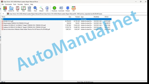
File List:
00 0302 512 3.pdf
Diesel engine TORION 1914 TORION 1812.pdf
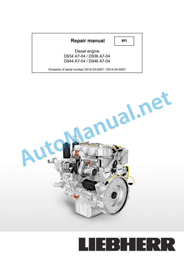
Liebherr LH-D934 A7 LH-D944 A7 Stage V TORION 1914 TORION 1812.pdf
Liebherr LH-D934 A7 LH-D944 A7 Stage IV TORION 1914 TORION 1812.pdf
Service Instructions Webasto Water heater Thermo Pro 90 Thermo Pro 90 HDD.pdf
00 0302 512 3.pdf:
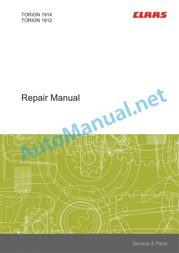
Repair Manual
Table of contents
Introduction
General information
Validity of manual
Using the manual
Text and figures
Document structure based on sub-assemblies
Search and find
Directions
Abbreviations
Technical terms
General repair instructions
Technical specifications
Information on technically correct repairs
Self-locking bolts
Liquid locking compound
Steel roller chains
Tensioning
Chain connector
Chain connector type E with spring
Chain connector type G with wire
Chain connector type S with cotter pins
Taper ring fasteners
Dismounting
Installing
Gib head key connections
Dismounting
Installing
Lock collar bearing
Dismounting
Installing
Adapter sleeve bearing
Dismounting
Installing
Chuck bushing
Removing
Dismounting of version A
Dismounting of version B
Installing
Chuck bushing version A
Chuck bushing version B
Circlips
Ferrule fittings
Screwing in
Leaky ferrule fittings
Sealing cone fittings
Hydraulic hoses
Hose placement
Treatment of sealing faces
Spare parts
Operating materials
Tightening torques
Tightening torques for metric standard and fine threads
Tightening torques for hydraulic fittings with ferrule
Tightening torques for screwed pipe connections with sealing cone joint and hydraulic threaded joints with soft core seal
Tightening torques for hydraulic male connectors SDS shape B and E
Tightening torques for hydraulic swivel screw fittings
Tightening torque for hollow screws (with copper sealing ring)
Tightening torques for hydraulic male connectors SDE shape H, with adjustable direction
Tightening torques for brake line screw fittings
Tightening torque for tubes with O-ring and union nuts
Tightening torques for worm drive hose clamps
Tightening torques for hose clamps with round pins
General tightening torques for Mannesmann-Rexroth
General tightening torques ZF
CCN explanation
CCN (CLAAS Component Number)
Electric systems standard
Hydraulic system standard
CCN (CLAAS Component Number)
General information
Safety and hazard information
Important
Signal word
General safety and accident prevention regulations
First-aid measures
Danger of injury from hydraulic liquid
Leaving the machine
Putting the machine out of operation
Jacking up the machine
Adjusting and maintenance work
Welding work
01 Engine
0102 Complete component
Diesel engine
Technical specifications
Work preparation
Removing
Installing
0125 Injection / Fuel system
Fuel tank
Technical specifications
Removing
Installing
Fuel filter
Technical specifications
Removing
Installing
Fuel cooler
Technical specifications
Removing
Installing
0135 Cooling system
Engine radiator
Technical specifications
Removing
Installing
Compensating tank
Technical specifications
Removing
Installing
Gear pump
Technical specifications
Removing
Installing
0145 Air intake
Air filter housing
Technical specifications
Removing
Installing
Charge air cooler
Technical specifications
Removing
Installing
Air cooler
Technical specifications
Removing
Installing
0150 Engine attachment parts
Electric starting motor
Technical specifications
Alternator
Technical specifications
Compressed-air compressor
Technical specifications
Work preparation
Removing
Installing
0165 Exhaust gas aftertreatment
Exhaust gas treatment – General
Work preparation
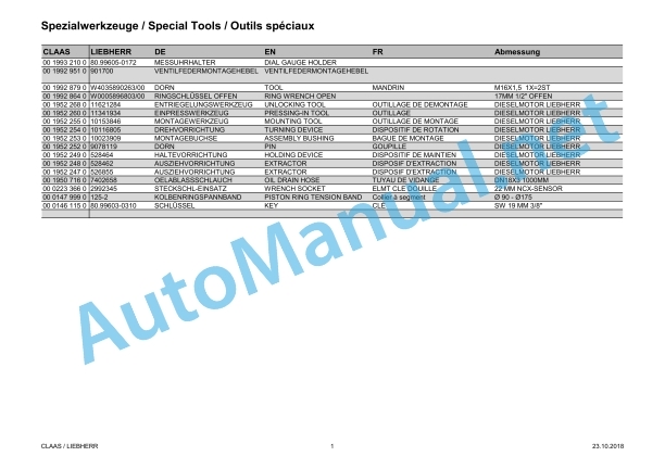
Special tool
Checking the purity of the urea solution
Checking the density of the urea solution
SCR catalytic converter
Technical specifications
Work preparation
Removing
Installing
Urea tank
Technical specifications
Removing
Installing
Withdrawal module
Technical specifications
Removing
Installing
Dosing unit
Technical specifications
Special tool
Removing
Installing
02 Gearbox / Clutch / Universal drive shaft
0202 Complete component
Technical specifications
Work preparation
Special tool
Removing
Installing
Technical specifications
Removing
Installing
Control unit
Technical specifications
Special tool
Removing
Installing
Speed sensors
Technical specifications
Removing
Installing
Pressurized oil pump
Technical specifications
Special tool
Removing
Installing
Drive and output flanges
Technical specifications
Special tool
Removing
Installing
Hydrostatic module
Technical specifications
Removing
Installing
0230 Mechanical gearbox
Pump transfer gearbox
Technical specifications
Work preparation
Removing
Installing
0255 Gearbox cooling system
Gearbox oil cooler
Technical specifications
Removing
Installing
0260 Universal drive shaft
Front axle universal drive shaft
Technical specifications
Removing
Installing
Rear axle universal drive shaft
Technical specifications
Removing
Installing
Gearbox drive universal drive shaft
Technical specifications
Special tool
Removing
Installing
03 Chassis
0316 Drive axle, front
Front drive axle
Technical specifications
Removing
Installing
Wheel bolts
Special tool
Installation instructions
Wheel hub
Technical specifications
Work preparation
Special tool
Removing
Disassembling
Assembling
Installing
Axle body
Technical specifications
Special tool
Removing
Installing
Differential gear
Technical specifications
Work preparation
Special tool
Disassembling
Assembling
Differential
Technical specifications
Special tool
Removing
Disassembling
Assembling
Installing
Determining the shims for installation
0317 Drive axle, rear
Rear drive axle
Technical specifications
Removing
Installing
Wheel bolts
Special tool
Installation instructions
Wheel hub
Technical specifications
Work preparation
Special tool
Removing
Disassembling
Assembling
Installing
Axle body
Technical specifications
Special tool
Removing
Installing
Differential gear
Technical specifications
Work preparation
Special tool
Disassembling
Assembling
Differential
Technical specifications
Special tool
Removing
Disassembling
Assembling
Installing
Determining the shims for installation
0340 Front wheels
Front wheels
Special tool
Installation
0345 Rear wheels
Rear wheels
Special tool
Installation
04 Brake
0405 Service brake
Service brake
Technical specifications
Installation instructions
Checking the tightness of the brake hydraulics
Checking the wear of brake discs
Brake pedal
Technical specifications
Removing
Installing
0415 Parking brake
Parking brake
Technical specifications
Removing
Installing
Venting the parking brake
Stop venting the parking brake
05 Steering
0505 Steering
Steering column
Technical specifications
Special tool
Removing
Disassembling
Assembling
Installing
Orbitrol
Technical specifications
Removing
Installing
Steering hydraulic cylinder
Technical specifications
Removing
Installing
Emergency steering pump
Technical specifications
Removing
Disassembling
Assembling
Installing
06 Lift device
0625 Tools
Technical specifications
Removing
Installing
0630 Lift arms
Lift arms
Technical specifications
Removing
Installing
Link plate
Technical specifications
Removing
Installing
Lift cylinder
Technical specifications
Special tool
Work preparation
Removing
Installing
Tipping cylinder
Technical specifications
Special tool
Work preparation
Removing
Installing
Guide lever
Technical specifications
Removing
Installing
Rotary angle sensor for lift arms
Technical specifications
Removing
Installing
Rotary angle sensor for tipping cylinder
Technical specifications
Removing
Installing
08 Drives
0800 Drive diagram
Drive diagram
09 Hydraulic system
0900 Hydraulic system – General
Hydraulic system – General
Special tool
Filling the accumulator
0905 Hydraulic oil tank
Hydraulic oil tank
Technical specifications
Special tool
Removing
Installing
Generating a vacuum
Stopping generating a vacuum
0907 Hydraulic oil cooler
Hydraulic oil cooler
Technical specifications
Removing
Installing
0910 Pumps
Working hydraulics pump
Technical specifications
Work preparation
Removing
Installing
Steering hydraulic pump
Technical specifications
Work preparation
Removing
Installing
10 Electrical / Electronic equipment
1005 Power supply
Technical specifications
Removing
Installing
1010 Central electrics
Central terminal compartment
Technical specifications
Removing
Installing
1020 Driving lights
Front drive lights
Technical specifications
Removing
Installing
Rear drive lights
Technical specifications
Removing
Installing
1025 Working lights
Work light
Technical specifications
Removing
Installing, left side
1030 Board computer / Indicators
Rear compartment monitoring
Technical specifications
Removing
Installing
1035 Operation / Multifunction control lever
Control lever
Technical specifications
Removing
Installing
Control panel
Technical specifications
Removing
Disassembling
Assembling
Installing
12 Cab / Operator’s platform
1210 Cab
Technical specifications
Removing
Installing
Roof covering
Technical specifications
Removing
Installing
Door lock / locking device
Technical specifications
Removing
Installing
Front windscreen wiper
Technical specifications
Removing
Installing
Rear wiper
Removing
Installing
1230 Seat
Driver’s seat
Technical specifications
Removing
Installing
1235 Cab heater
Heater/air conditioning unit
Technical specifications
Work preparation
Removing
Installing
1240 Air condition
Air conditioner compressor
Technical specifications
Removing
Installing
Anti-icing protection sensor
Removing
Installing
75 Central lubrication system
7505 Reservoir / Pump
Grease container
Technical specifications
Removing
Installing
7510 Distributor
Lubricant distributor
Technical specifications
Removing
Installing
80 Various components / Machine body
8015 Access
Cab access
Technical specifications
Removing, left side
Removing, right side
Installing, left side
Installing, right side
8025 Panellings / Hoods
Engine bnet
Technical specifications
Removing
Instaing
Engine bonnet linear motor
Technical specifications
Removing
Installing
Side panel
Technical specifications
Removing the left side panel
Installing the left side panel
Removing the right side panel
Installing the right side panel
Protecting covers
Technical specifications
Removing
Installing
8030 Mud guards
Wheel case extension
Removing
Installing
8035 Ballast / Additional weight
Ballast weight
Technical specifications
Removing the left ballast weight
Installing the left ballast weight
Removing the right ballast weight
Installing the right ballast weight
95 Maintenance parts overview
9599 Maintenance jobs
Maintenance position 1
Maintenance position 2
Adjusting the valve lash
Special tool
Bleeding the fuel system
Replacing the fuel prefilter insert
Changing the fuel fine filter element
Changing the diesel engine oil
Draining oil
Topping up oil
Changing the diesel engine oil filter
Replacing the filter element of the diesel engine oil separator
Changing the coolant
Draining the coolant
Topping up coolant
Checking the V-belt of the diesel engine
Changing the diesel engine belt
Checking the intake system and the exhaust system
Checking the intake system
Checking the exhaust system
Checking the exhaust system with diesel particulate filter
Check the fastening of diesel engine control units and the cable connections.
Changing the diesel engine heater flange
Cleaning the filter module of the diesel particulate filter
Checking the urea tank ventilation
Changing the gear oil and the gearbox oil filter
Work preparation
Changing the hydrostatic oil filter of the gearbox
Changing the pump transfer gearbox oil
Draining oil
Topping up oil
Testing and measuring the ground drive
Checking the universal drive shafts
Changing the axles’ oil
Draining oil
Topping up oil
Checking the wear of service brake discs
Checking the parking brake wear
Work preparation
Checking the brake lining wear
Checking the operating clearance
Replacing the brake linings
Adjusting the operating clearance
Checking the parking brake emergency operation
Testing and measuring the brake system
Testing and measuring the steering system
Checking the bucket bearing sleeves on the lift arms
Checking the bucket stops
Check the bucket stops when installing directly
Checking the bucket stops on the quick-hitch plate
Performing a hydraulic oil analysis
Changing the hydraulic oil
Draining the hydraulic oil
Topping up hydraulic oil
Changing the hydraulic oil tank fresh air filter element
Changing the hydraulic oil tank return line filter cartridge
Drain the condensate and sediment from the hydraulic oil tank
Checking and measuring the working hydraulics
Checking the liquid level of batteries
Replacing the forward/reverse control rocker switch and the multifunction handle cap
Checking the compressed-air system
Changing the compressed-air system air dryer
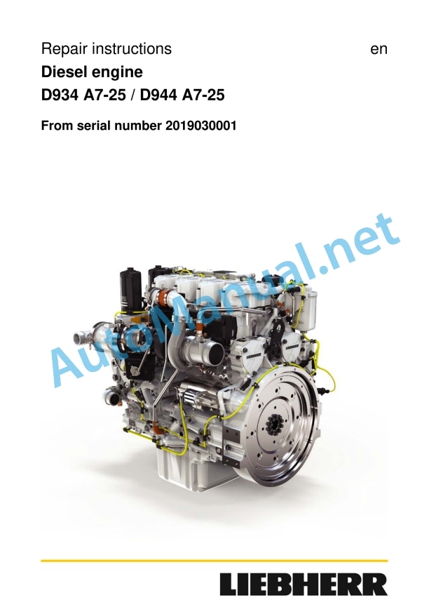
Liebherr LH-D934 A7 LH-D944 A7 Stage V TORION 1914 TORION 1812.pdf:
Repair instructions
Only for the United States
Change history
About the document
Work instructions
Spare parts
Lubricating and operating fluids
Usage instructions
Graphic symbols in these instructions
Changes, conditions, copyright
Contents
1 Product description
1.1 Technical description
1.1.1 Engine components
1.1.2 Exhaust aftertreatment system SCRFilter (single-flow)
1.1.3 Reduction agent pump
1.1.4 Engine type itemization
1.1.5 Firing order, cylinder designation and engine serial number
1.1.6 Direction of rotation
1.1.7 Company nameplate
1.1.8 Engine control unit type plate ECU3
1.1.9 Exhaust aftertreatment system type plate
1.2 Technical data
1.2.1 Cylinder liner projection
1.2.2 Valve clearance
1.2.3 Piston ring end gap
1.2.4 Thermostat start of opening
1.3 Functional description
1.3.1 Fuel system
1.3.2 Lubrication system
1.3.3 Cooling system
1.3.4 Assignment of the channels in the crankcase and cylinder head
1.3.5 Exhaust aftertreatment system SCRFilter (single-flow)
1.3.6 Reduction agent pump
2 Safety
2.1 Labeling of warnings
2.1.1 Additional labels
2.2 Target group
2.3 Intended use
2.4 Foreseeable misuse
2.5 General safety instructions
2.6 Preventing personal injuries
2.6.1 Bruises
2.6.2 Burns and scalds
2.6.3 Fires and explosions
2.6.4 Poisoning
2.6.5 High-pressure injection (liquids at high pressure can squirt out)
2.6.6 Electrical energy
2.6.7 Danger due to noise
2.7 Personal protective equipment
2.8 Operating areas and maintenance areas
2.8.1 Safety instructions
2.8.2 Operating areas
2.8.3 Maintenance areas
2.8.4 Securing and releasing the diesel engine against accidental start-up
2.8.5 Emergency stop
2.9 Signage
2.10 Preventing property damage
3 Repair work
3.1 Removing and installing the cover (variant 1)
3.1.1 Removing the cover
3.1.2 Installing the cover
3.2 Removing and installing the cover (variant 2)
3.2.1 Removing the cover
3.2.2 Installing the cover
3.3 Cylinder head cover
3.3.1 Removing and installing the cylinder head cover
3.4 Cylinder head
3.4.1 Checking and setting the valve clearance
3.4.2 Rocker arm bracket and push rods
3.4.3 Removing and installing the valve bridges
3.4.4 Removing and installing the cylinder head
3.4.5 Valves and valve stem seal
3.4.6 Removing and installing the roller plunger
3.4.7 Removing and installing the camshaft
3.5 Driving gear
3.5.1 Piston with connecting rod
3.5.2 Piston rings
3.5.3 Removing and installing the cylinder liner
3.5.4 Checking the projection of the cylinder liners
3.5.5 Removing and installing the belt pulley
3.5.6 Ancillary support housing side radial shaft sealing ring
3.5.7 Removing and installing the ancillary support housing
3.5.8 Flywheel
3.5.9 Removing and installing the flywheel housing (variant 1)
3.5.10 Removing and installing the flywheel housing (variant 2)
3.5.11 Removing and installing the flywheel housing (variant 3)
3.5.12 Removing and installing the flywheel housing (variant 4)
3.5.13 Crankshaft
3.6 Fuel system
3.6.1 Safety instructions for working on the fuel system
3.6.2 Removing and installing the fuel lines
3.6.3 Removing and installing the fuel return line
3.6.4 Reducing the pressure in the fuel system
3.6.5 Removing and installing the fuel injection pipe
3.6.6 Removing and installing the injection pipes
3.6.7 Removing and installing the fuel rail
3.6.8 Removing and installing the pressure pipe socket and injector
3.6.9 Fuel high pressure pump
3.6.10 Drive for high pressure pump
3.7 Belt drive
3.7.1 Removing and installing the V-ribbed belt
3.7.2 Remove and install the tension pulley (self-tensioning)
3.7.3 Removing and installing the deflection pulley
3.8 Charge air system
3.8.1 Removing and installing the charge air pipe
3.8.2 Removing and installing the intermediate flange
3.8.3 Air intake manifold
3.8.4 Removing and installing the intake manifold
3.9 Exhaust system
3.9.1 Exhaust gas stub
3.9.2 Exhaust gas turbocharger
3.10 Engine oil system
3.10.1 Removing and installing the end control valve
3.10.2 Removing and installing the oil mist separator return line
3.10.3 Crankcase ventilation
3.10.4 Oil cooler
3.10.5 Oil pan
3.10.6 Engine oil pump
3.10.7 Removing and installing the oil pump
3.10.8 Removing and installing the piston cooling nozzle
3.11 Cooling system
3.11.1 Removing and installing the pipeline and coolant venting pipe
3.11.2 Coolant manifold
3.11.3 Coolant pump
3.11.4 Thermostat
3.12 Auxiliary output
3.12.1 Air conditioning compressor (optional)
3.12.2 Air compressor (optional)
3.12.3 Removing and installing power take off 1
3.12.4 Removing and installing power take off 3
3.12.5 Removing and installing power take off 4
3.13 Electrical system
3.13.1 Removing and installing the heating flange
3.13.2 Alternator
3.13.3 Removing and installing the starter motor
3.13.4 Installing the starter motor
3.13.5 Engine control unit
3.13.6 Sensors
3.13.7 Cable harness
3.14 SCRF exhaust aftertreatment system
3.14.1 Removing and installing the SCRF inlet module (single-flow)
3.14.2 Removing and installing the SCRF outlet module (single-flow)
3.14.3 Removing the pressure measurement lines
3.14.4 Removing the filter module (single-flow)
3.14.5 Installing the filter module (single-flow)
3.14.6 Installing the pressure measurement line
3.14.7 Exhaust regulation sensors
3.14.8 Removing and installing the reduction agent pump
3.14.9 Removing and installing the mixing pipe
3.14.10 Removing and installing the reduction agent injector
3.14.11 Removing and installing the diesel oxidation catalyst
3.14.12 Removing and installing the sensor pipe
4 Tools and devices
4.1 Tools
4.1.1 Special tools
4.1.2 Diagnostic tools
4.2 Devices
4.2.1 Lifting traverse with two-point-raising (basic version)
4.2.2 Lifting traverse with two-point-raising
4.2.3 Engine assembly stand
4.2.4 Engine assembly stand and adapter
4.2.5 Transport device
5 Assembly agents
6 Appendix
6.1 Tightening torques
6.1.1 For hex bolts / cylinder screws / external hex bolts
6.1.2 For locking screws and banjo bolts
6.1.3 Standard torques for metric flange connections
6.1.4 Metric screw connection series L (light) (up to 500 bar/7252 Psi)
6.1.5 Metric screw connection series S (heavy) (up to 800 bar/11603 Psi)
6.1.6 Inch screw connection series L (light) (up to 500 bar/7252 Psi)
6.1.7 Inch screw connection series S (heavy) (up to 800 bar/11603 Psi)
6.1.8 Metric thread unit series L (light) (up to 500 bar/7252 Psi) for aluminum
Liebherr LH-D934 A7 LH-D944 A7 Stage IV TORION 1914 TORION 1812.pdf:
1 General information
1.1 Structure of this manual
1.2 Important notes in this manual
1.2.1 Identification of operational safety instructions
1.2.2 Additional identifications
1.3 Safety instructions
1.3.1 General safety instructions
1.3.2 Preventing personal injuries
1.3.3 Preventing property damage
1.4 Safety instructions for working on the fuel and injection system
1.4.1 General safety instructions
1.4.2 Preventing personal injuries
1.4.3 Preventing property damage
1.5 Safety instructions for working on the exhaust after-treatment system (SCR system)
Definition of terms
1.5.1 Reducing agent
1.5.2 General safety instructions
1.5.3 Preventing personal injuries
1.5.4 Preventing property damage
1.6 Engine diagrams and engine components
Flywheel side view
Unit carrier side view
6-cylinder wheel drive view
4-cylinder wheel drive view
1.7 Technical data
1.7.1 Engine, general
1.7.2 Standard torques for screw connections
1.7.3 Standard torques for screw plugs and banjo screws
1.7.4 Standard torques for metric screw fittings
1.7.5 Standard torques for imperial screw fittings
1.7.6 Standard torques for cutting ring screw fittings
1.7.7 Standard torques for triple-lock screw fittings
1.7.8 Standard torques for VSTI screw plugs
1.8 Special torques, tensioning instructions, instructions for mounting and installation instructions
1.8.1 Cleaning and locking agents, greases
1.8.2 Special torques for cylinder head engine control unit and valves
Tensioning instruction for rocker arm bracket
Installation and tensioning instruction for cylinder head
Tensioning instruction for injector sleeve
Tensioning instruction for camshaft gear
1.8.3 Special torques for the engine
Tensioning instruction for crank
Tensioning instruction for crankshaft attachments
Tensioning instruction for unit carrier
Tensioning instruction for flywheel
Tensioning instruction for flywheel
Tensioning instruction for flywheel housing
Tensioning instruction for main bearing
1.8.4 Special torques for fuel and injection system
Tensioning instruction for injection lines
Installation and tensioning instruction for injector and pressure pipe branch
Tensioning instruction for fuel fine filter
Tensioning instruction for fuel high pressure pump
1.8.5 Special torques for charge air and exhaust system
Tensioning instruction for exhaust pipe
Tensioning instruction for exhaust branch
Tensioning instruction for turbocharger and flange on turbocharger
Tensioning instruction for SCR catalytic converter
Tensioning instruction for air compressor nut
Tensioning instruction for air compressor M6 screw
Tensioning instruction for reducing agent extraction module
Tensioning instruction for SCR injector
Tensioning instruction for SCR profile clip
Instructions for mounting high temperature sensor
Instructions for mounting lambda NOx sensor
Instructions for mounting NH3 sensor
Instructions for mounting outside temperature sensor
Instructions for mounting humidity sensor
1.8.6 Special torques for the electrical system
Tensioning instruction for heating flange
Tensioning instruction for alternator electrical connection
Tensioning instruction for starter individual operation
Tensioning instruction for sensors
Tensioning instruction for engine control units attachment
1.8.7 Special torques for the lubrication system
Tensioning instruction for oil cooler housing screws
Cold start valve
Tensioning instruction for valve
Tensioning instruction for cold start valve default setting
Tensioning instruction for piston cooling injector
1.8.8 Special torques for the auxiliary output, air compressor
Tensioning instruction for proximity switch switchable auxiliary output
Tensioning instruction for M52x1.5 ring auxiliary output
Tensioning instruction for M40x1.5 ring auxiliary output
1.9 Fuel diagram
1.10 Lubricating oil diagram
1.11 Coolant diagram
1.11.1 Coolant diagram, general overview
1.11.2 Coolant circuit, engine
Coolant circuit, unit carrier side view
Coolant circuit, cylinder head
1.12 Assigning the channels in the crankcase and the cylinder head
1.13 Transport device and fastening parts
1.13.1 Removing and installing the transport device and fastening parts
1.14 Tools
1.14.1 Special tools
Lifting traverse
Engine assembly stand
Lifting device for flywheels (SAE0, SAE1 and SAE2)
Turning devices
Assembly bolt
Pivot bracket devices
Torx tools
Removing and installing the cylinder liner
Checking the cylinder liners’ projection
Removing and installing the unit carrier
Removing and installing the flywheel housing
Removing and installing the front crankshaft seal
Removing and installing the crankshaft
Removing and installing the piston with crank and piston rings
Removing and installing the piston rings
Removing and installing the valve stem seal, valve springs, valves
Removing and installing the mass balancing shafts
Removing and installing the camshaft
Removing and installing the injection line
Removing and installing the pressure pipe branch and injector
Removing and installing the injector sleeve
Removing and installing the flywheel
Removing and installing the rear crankshaft seal
Reducing agent pump
Auxiliary outputs
2 Cylinder head, engine control unit and valves
2.1 Removing and installing the cylinder head cover
2.2 Removing and installing the rocker arm bracket and push rods
2.3 Removing and installing the valve bridge (engines with and without ABS)
2.4 Removing and installing the cylinder head
Installation and tensioning instruction for cylinder head
2.5 Removing and installing the injector sleeve
Tensioning instruction for injector sleeve
2.6 Removing and installing the valve stem seal, valve springs, valves
2.6.1 Remove
2.6.2 Installing
2.6.3 Removing and installing the valve stem seal without removing the cylinder head
2.7 Removing and installing the roller tappet (valve controller)
2.8 Removing and installing the camshaft
Tensioning instruction for camshaft gear
2.8.1 Remove
If present: Gear wheel on the unit carrier side
2.8.2 Installing
If present: Gear wheel on the unit carrier side
3 Driving gear
3.1 Removing and installing the piston with crank and piston rings
3.1.1 Overview
3.1.2 A: Removing and installing the piston with crank from the engine
Tensioning instruction for crank
Installing
3.1.3 B: Removing and installing the piston rings
Installing
3.1.4 C: Removing and installing the pistons
3.2 Removing and installing the cylinder liner
Note on the special tools
3.2.1 Checking the cylinder liners’ projection
3.3 Removing and installing the crankshaft attachments
Tensioning instruction for crankshaft attachments
3.4 Removing and installing the front crankshaft seal
3.4.1 General instructions
3.4.2 Remove
3.4.3 Installing
3.5 Removing and installing the unit carrier
Tensioning instruction for unit carrier
3.6 Removing and installing the flywheel
Flywheel without membranes
Flywheel with membranes
Tensioning instruction for flywheel
Tensioning instruction for flywheel
3.6.1 Remove
3.6.2 Installing
Checking rotation
3.6.3 Removing and installing the starting gear ring
3.7 Removing and installing the rear crankshaft seal
3.7.1 General instructions
3.7.2 Remove
3.7.3 Installing
3.8 Removing and installing the flywheel housing
Tensioning instruction for flywheel housing
3.9 Removing and installing the top right intermediate wheel
3.10 Removing and installing the top middle intermediate wheel
3.11 Removing and installing the crankshaft
Tensioning instruction for main bearing
3.11.1 Remove
3.11.2 Installing
Checking the crankshaft’s axial play
3.12 Removing and installing the crankshaft gear wheel
4 Fuel and injection sy
John Deere Repair Technical Manual PDF
John Deere Repair Technical Manual PDF
John Deere Repair Technical Manual PDF
John Deere Repair Technical Manual PDF
John Deere Repair Technical Manual PDF
John Deere Transmission Control Unit Component Technical Manual CTM157 15JUL05
John Deere Repair Technical Manual PDF
John Deere Repair Technical Manual PDF
John Deere Parts Catalog PDF
John Deere Tractors 6300, 6500, and 6600 Parts Catalog CQ26564 (29SET05) Portuguese
John Deere Repair Technical Manual PDF
John Deere POWERTECH E 4.5 and 6.8 L Diesel Engines TECHNICAL MANUAL 25JAN08
John Deere Parts Catalog PDF
John Deere Tractors 7500 Parts Catalog CPCQ26568 30 Jan 02 Portuguese

