Claas Tucano 480-470 (840) Combines Operator Manual EN
$50.00
- Model: Tucano 480-470 (840) Combines
- Type Of Manual: Operator Manual
- Language: EN
- Format: PDF(s)
- Size: 376 MB
File List:
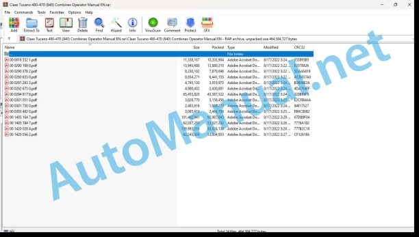
00 0018 552 1.pdf
00 0290 198 0.pdf
00 0290 378 2.pdf
00 0290 635 0.pdf
00 0291 263 3.pdf
00 0292 675 0.pdf
00 0294 817 9.pdf
00 0301 051 0.pdf
00 0301 730 0.pdf
00 0303 482 0.pdf
00 1405 164 7.pdf
00 1405 184 7.pdf
00 1420 028 4.pdf
00 1420 056 2.pdf
00 0018 552 1.pdf:
TELEMATICS Website
Table of contents
1 About this Concise Operator’s Manual
1.1 Notes on the manual
1.1.1 Validity of manual
1.1.2 Notes regarding the Concise Operator’s Manual
1.1.3 Notes on warranty
2 Safety
2.1 Intended use
2.1.1 Proper use
3 Product description
3.1 Overview and method of operation
3.1.1 TELEMATICS product variants
3.1.2 TONI (TELEMATICS on implements)
3.1.3 Fleet View
3.1.4 TELEMATICS basic
3.1.5 TELEMATICS advanced
3.1.6 TELEMATICS professional
3.1.7 TELEMATICS app
4 Operating and control elements
4.1 TELEMATICS overview
4.1.1 Illustration conventions of buttons and navigation elements
4.1.2 Symbols and colours
4.2 Menu structure
4.2.1 Start screen
4.2.2 TELEMATICS website site map
4.2.3 Main menu overview
4.2.4
4.2.5
4.2.6
00 0290 198 0.pdf:
1 Einleitung
1.1 Allgemeine Hinweise
1.1.1 Handhabung der Anleitung
Texte und Abbildungen
Richtungsangaben
1.1.2 Gltigkeit der Anleitung
2 Sicherheit
2.1 Beachten
2.1.1 Besonders zu beachten
2.1.2 Kennzeichnung von Warn- und Gefahrenhinweisen
3 Lieferumfang
3.1 Raupenlaufwerk
3.1.1 Nachrstsatz
4.1 Allgemeine Hinweise
4.1.1 Allgemeine Warnhinweise Umbau
4.2 Lenkachsenerhhung fr Raupenlaufwerk TUCANO 450 / 440
4.2.1 Lieferumfang kontrollieren
4.2.2 Lenkachsenerhhung anbauen
4.3 Installation for Raupenlaufwerk TUCANO 450 / 440
4.3.1 Lieferumfang kontrollieren
4.3.2 Unterbau anbauen
4.4werke fr Raupenlaufwerk TUCANO 450 / 440
4.4.2 Laufwerke anbauen
4.5 Ketten fr Raupenlaufwerk TUCANO 450 / 440
4.5.1 Lieferumfang kontrollieren
4.5.2 Ketten anbauen
4.6 Aufstiegsleiter fr Raupenlaufwerk TUCANO 450 / 440
4.6.1 Lieferumfang kontrollieren
4.6.2 Wishing Leiter anbauen
4.6.3 Probelauf vorbereiten und durchfhren
5 Einstellung Arbeitseinsatz
5.1 Allgemeine Hinweise
5.1.1 Allgemeine Warnhinweise Einstellungen Arbeitseinsatz
5.2 Fahrwerk TUCANO 450 / 440
5.2.1 Raupenlaufwerke abbauen
5.3 Fahrwerk TUCANO 450 / 440
5.3.1 Raupenlaufwerke anbauen
6 Schmierplan Raupenlaufwerk
6.1 Schmierstellen
6.1.1 Schmierstoffe
6.1.2 Schmier interval
6.1.3 Schmierstellen – 10 h
1 Introduction
1.1 General Information
1.1.1 How to use this manual
Texts and figures
Directions
1.1.2 Validity of manual
2 Safety
2.1 Important
2.1.1 Important information
2.1.2 Identification of warning and da signs
3 Package list
3.1 Track roller unit
3.1.1 Supplementasion
4.1 General Information
4.1.1 General warnings for conversion
4.2 Rear axle height increase for track roller unit TUCANO 450 / 440
4.2.1 Checking the shipping package
4.2.2 Fitting the rear axle height increase
4.3 Substructure for track roller unit TUCANO 450 / 440
4.3.1 Checking the shipping package
4.3.2 Fitting the substructure
4.4 Traveling gears for track roller unit TUCANO 450 / 440
4.4.1 Checking the shipping package
4.4.2 Installing the traveling gears
4.5 Tracks for track roller unit TUCANO 450 / 440
4.5.1 Checking the shipping package
4.5.2 Fitting the tracks
4.6 Ladder for track roller unit TUCANO 450 / 440
4.6.1 Checking the shipping package
4.6.2 Installing the front ladder
4.6.3 Prepare and carry out a test run
5 Fieldwork settings
5.1 General Information
5.1.1 General warnings for fieldwork settings
5.2 Chassis of TUCANO 450 / 440
5.2.1 Removing the track roller units
5.3 Chassis of TUCANO 450 / 440
5.3.1 Fitting track roller units
6 Lubrication chart of track roller unit
6.1 Lubrication points
6.1.1 Lubricants
6.1.2 Greasing cycles
6.1.3 Lubrication points – 10 h
1 Introduction
1.1 General indications
1.1.1 Using the instructions
Texts and images
Directional indications
1.1.2 Validity of the manual
2 Safety Medications
2.1 Observe
2.1.1 Especially important
2.1.2 Reporting of warnings and warnings
3 Suminister Council
3.1 Orugas running train
3.1.1 Rear assembly work
4 Transformation
4.1 General indications
4.1.1 General information on Transformation advice
4.2 Elevating the direct drive for the TUCANO 450 / 440 wheel train
4.2.1 Check the chief executive officer
4.2.2 Mount the elevation of the steering wheel
4.3 Lower structure for the TUCANO 450 / 440 running gear
4.3.1 Check the chief executive officer
4.3.2 Assemble the lower structure
4.4 Running trains for the TUCANO 450 / 440 running train
4.4.1 Check the chief executive officer
4.4.2 Mount the running gear
4.5 Chains for the TUCANO 450 / 440 wheel train
4.5.1 Check the chief executive officer
4.5.2 Assemble the cadenas
4.6 Access ladder for the TUCANO 450 / 440 running gear
4.6.1 Check the chief executive officer
4.6.2 Assemble the ladder
4.6.3 Prepare and carry out an operational test
5 Adjustment in operational service
5.1 General indications
5.1.1 General warning indications Adjustments for working use
5.2 Chasis TUCANO 450 / 440
5.2.1 Disassemble the trains of rodaje de orugas
5.3 Chasis TUCANO 450 / 440
5.3.1 Mount the wheel trains
6 Diagram for engraving the train of wheels of wheels
6.1 Entry points
6.1.1 Lubricants
6.1.2 Engaging intervals
6.1.3 Engaging points – 10 h
1. Introduction
1.1 General indications
1.1.1 Application of the user manual
Texts and figures
Direction data
1.1.2 Validity of the user manual
2 Safety
2.1 To be observed
2.1.1 Important warnings
2.1.2 Warning and danger signs
3 Total supply
3.1 Track carriage
3.1.1 Upgrade kit
4.1 General indications
4.1.1 General warnings for modification
4.2 Raising the steering axle for the TUCANO 450 / 440 track carriage
4.2.1 Check the delivery assembly
4.2.2 Fitting the steering axle riser
4.3 Lower structure for the TUCANO 450 / 440 track carriage
4.3.1 Check the delivery assembly
4.3.2 Assembly of the lower structure
4.4 Trolleys for TUCANO 450 / 440 tracks
4.4.1 Check the delivery assembly
4.4.2 Assembling the trolleys
4.5 Chains for the TUCANO 450 / 440 track carriage
4.5.1 Check the delivery assembly
4.5.2 Assembly of catenaries
4.6 Ladder for the TUCANO 450 / 440 track trolley
4.6.1 Check the delivery assembly
4.6.2 Assembling the front ladder
4.6.3 Preparation and execution of operational tests
5 Adjustment for practical use in the field
5.1 General indications
5.1.1 General warnings for use in the field
5.2 TUCANO 450 / 440 axle
5.2.1 Disassembly of the track carriage
5.3 TUCANO 450 / 440 axle
5.3.1 Assembling the track carriage
6 Track carriage lubrication diagram
6.1 Greasing points
6.1.1 Lubricants
6.1.2 Lubrication intervals
6.1.3 Lubrication points – 10 h
2.????? ??? ??????????? ????????? TUCANO 450 / 440
4.6.1 ?????? ????? ????????
4.6.2 ?????????? ????? ????????
4.6.3 ?????????? is ?????????? ??????? ?????
5 ???????? ??? ??????
5.1 ????? ????????
5.1.1 ????? ????????? ??? ???????? ???????? ??? ????????????
5.2 ??????? ???????? TUCANO 450 / 440
5.2.1 ????? ?????????? ?????????
5.3 ??????? ???????? TUCANO 450 / 440
5.3.1 ?????????? ?????????? ?????????
6 ???? ?????? ??????????? ?????????
6.1 ????? ??????
6.1.1 ????????? ????????
6.1.2 ???????? ??????
6.1.3 ????? ?????? – 10 ?????
00 0290 378 2.pdf:
Contents
1 Introduction
1.1 General Information
1.1.1 Validity of manual
2 Sectional view of machine
2.1 Attachment parts / machine body
2.1.1 Access to the workplace and maintenance areas
3 Safety
3.1 General Information
3.1.1 Intended use
3.1.2 Reasonable foreseeable misuse
3.1.3 Decommissioning and disposal
3.2 Safety decals
3.2.1 Separation
3.2.2 Crop racle / straw receptacle
4 Specifications
4.1 TUCANO 450 – Type 840
4.1.1 General information
4.1.2 Engine
4.1.3 Chassis
4.1.4 Tyre pressures
4.1.5 Chassis track width
4.1.6 Brake
4.1.7 Steering
4.1.8 Electric system / Electronics
4.1.9 Cab / Operator’s platform
4.1.10 Intake
4.1.11 Threshing mechanism
4.1.12 Separation
4.1.13 Cleaning unit
4.1.14 Grain delivery
4.1.15 Grain delivery dimensions
4.1.16 Attachment parts / machine body dimensions
4.1.17 Attachment parts / machine body weights
5 Prior to initial operation
5.1 General Information
5.1.1 General warnings Prior to initial operation
5.2 Various components / Machine body
5.2.1 Opening / closing the rotor drive side panel
5.2.2 Using rear ladder
10 Fieldwork settings
10.1 General Information
10.1.1 General warnings Fieldwork
10.2 Feeder unit
10.2.1 Adjusting the speed of front attachment drive belt (R1)
10.2.2 Adjusting the cutting angle of the V-type feed rake conveyor (optional equipment) to its basic adjustment
12 Fieldwork
12.1 General Information
12.1.1 General warnings Fieldwork
12.2 Feeder unit
12.2.1 Adjusting the cutting angle of the V- type feed rake conveyor (optional equipment)
12.3 Separation
12.3.1 Adjusting the rotor speed
12.3.2 Observe the straw blockage warning downstream of the separation stage
12.3.3 Adjusting the separation performance monitor display
12.4 Crop receptacle / straw receptacle
12.4.1 Putting the straw chopper into operation (swinging the standard spreader to chopping position)
12.4.2 Putting the straw chopper out of operation (swinging the standard spreader to swathing position)
12.5 Sieve charts / threshing charts
12.5.1 Threshing chart (TUCANO 450)
14 Maintenance
14.1 General Information
14.1.1 General warnings Maintenance
14.2 Maintenance schedule
14.2.1 Service intervals
14.3 Lubricants chart
14.3.1 Lubricants
14.4 Engine
14.4.1 Fill up the machine’s fuel tank
14.4.2 Cleaning the additional fuel tank filling screen (accessory)
14.4.3 Changing the fuel filter (additional fuel tank, accessory)
14.4.4 Changing the fuel filter (CATERPILLAR C-9)
14.4.5 Bleeding the fuel system (CATERPILLAR C-9)
14.4.6 Checking the diesel engine oil level (CATERPILLAR C-9)
14.4.7 Changing the diesel engine oil / oil filter (CATERPILLAR C-9)
14.5 Brake
14.5.1 Adjusting the foot brake
14.5.2 Checking the wheel chocks / brake shoes
14.5.3 Changing the wheel chocks / brake shoes
14.6 Drive belts / drive chains
14.6.1 General warnings
14.6.2 Drive diagram, left side of TUCANO 450
14.6.3 Drive diagram, right side of TUCANO 450
14.6.4 Adjusting belt (R20)
14.6.5 Adjusting belt (R22)
14.6.6 Adjusting belt (R23)
14.6.7 Removing belt (R24)
14.6.8 Installing belt (R24)
14.6.9 Adjusting belt (R24)
14.6.10 Adjusting belt (R25)
14.6.11 Removing belt (R43)
14.6.12 Installing belt (R43)
14.6.13 Adjusting belt (R49)
14.6.14 Removing belt (R50)
14.6.15 Installing belt (R50)
14.6.16 Adjusting belt (R50)
14.7 Separation
14.7.1 Checking the rotor gearbox oil level
14.7.2 Draining the rotor gearbox oil
14.7.3 Topping up rotor gearbox oil
14.7.4 Cleaning the separation throughput monitor sensor
14.7.5 Cleaning the rotor
15 Lubrication chart
15.1 Lubrication points
15.1.1 General warnings Lubrication chart
15.1.2 Lubricants
15.1.3 Greasing cycles
15.1.4 Lubrication points – 10 h on the left
15.1.5 Lubrication points – 10 h on the right
15.1.6 Lubrication points – 50 h on the left
15.1.7 Lubrication points – 100 h on the left
15.1.8 Lubrication points – 500 h on the left
15.1.9 Lubrication points – 500 h on the right
00 0291 263 3.pdf:
TUCANO 470 – 320
Table of contents
1 To this operator’s manual
1.1 General Information
1.1.1 General instructions
1.1.2 Validity of manual
1.1.3 Handling of manual
1.1.4 Symbols and notes
1.1.5 Machine equipment
1.1.6 Technical specifications
2 Safety
2.1 Safety decals on the machine
2.1.1 Crop discharge / straw discharge
2.1.2 Safety decals
3 Machine description
3.1 Overview and method of operation
3.1.1 Engine overview
4 Operating and control elements
4.1 Cab / Operator’s platform
4.1.1 Vehicle information unit
4.2 Board computer / Indicators
4.2.1 Vehicle control display overview
5 Technical specifications
5.1 TUCANO 470 / 450 / 440 / 430 / 340 / 320 – Type 840 / 839 /838 / 834 / 832
5.1.1 Engine
5.1.2 Electrical/electronic equipment
5.1.3 Attachment parts / machine body weights
6 Machine preparation
6.1 Shutting down and securing the machine
6.1.1 Switch off and secure the machine
6.2 Loading the machine
6.2.1 Use of lifting gears
7 Operation
7.1 General Information
7.1.1 General warnings
7.2 Crop discharge / Swath discharge
7.2.1 Adjusting the straw chopper speed (TUCANO 450 / 440 / 430 / 340 / 320, drive on left side)
Reduce the straw chopper speed
Increasing the straw chopper speed
7.2.2 Straw chopper overview
7.2.3 Converting the straw chopper to swathing position
7.2.4 Converting the straw chopper to chopping position
7.2.5 Adjusting the inclination (Special Cut deflector plate spreader)
8 Faults and remedies
8.1 General Information
8.1.1 General warnings
8.2 Cab / Operator’s platform
8.2.1 Basic central terminal compartment
8.3 Electrical / Electronic equipment
8.3.1 Vehicle main fuse
8.3.2 Installation position of battery
8.3.3 Assist-starting (12 V / 24 V)
Assist-starting (12 V / 24 V)
Diesel engine assist-starting
9 Maintenance
9.1 General Information
9.1.1 General warnings
9.1.2 Permissible fuels
9.1.3 Urea solution
Use of urea solution
Purity / urea solution standard
Storage of urea solution in tanks / containers
Properties of urea solution at high / low outside temperatures
9.1.4 Welding work on combine harvester
9.2 Operating utilities
9.2.1 Lubricants
9.3 Service intervals
9.3.1 Every 10 operating hours or daily
9.3.2 Every 500 operating hours or annually
9.3.3 Every 1000 operating hours or every 2 years
9.3.4 Every 3 years
9.4 Engine
9.4.1 Cleaning the diesel engine surroundings
9.4.2 Refilling a machine with urea solution
9.4.3 Replacing the urea solution filter
9.5 Drives
9.5.1 General warnings
9.5.2 Adjusting the drives
9.5.3 Adjusting belt (R26)
9.5.4 Removing belt (R27)
9.5.5 Adjusting belt (R27)
9.5.6 Removing belt (R53)
9.5.7 Installing belt (R53)
9.5.8 Adjusting belt (R53)
9.6 Various components / Machine body
9.6.1 Replacing the dry-type air cleaner in the compressed air cleaning system
9.7 Lubrication chart
9.7.1 Lubrication points – 100 h left
9.7.2 Lubrication points – 500 h left
00 0292 675 0.pdf:
LEXION 770 – 620TUCANO 470 – 320
Table of contents
1 To this operator’s manual
1.1 General Information
1.1.1 Validity of manual
1.1.2 Symbols and notes
2 Operating and control elements
2.1 Cab / Operator’s platform
2.1.1 CEBIS control panel
2.2 Board computer CEBIS
2.2.1 General instructions – CEBIS
2.2.2 Vehicle control display overview
2.2.3 Vehicle control display overview
2.2.4 Harvest display overview
2.2.5 CRUISE PILOT harvest display overview
2.2.6 CEBIS direct menu overview
2.2.7 Understanding CEBIS fault code information
Understanding the type of fault code information
Understanding the format of fault code information
Clearing fault code information
Viewing the alarm history
Viewing active alarms
2.2.8 Symbols in windows
2.2.9 CEBIS direct menu
2.2.10 HOTKEY direct menu
2.2.11 Quick access menu
2.2.12 Main menu
2.2.13 Front attachment menu
2.2.14 Driving menu
2.2.15 AUTO PILOT menu
2.2.16 Machine settings menu
2.2.17 Crop settings menu
2.2.18 Recorder menu
2.2.19 Maintenance menu
2.2.20 CEBIS menu
00 0301 051 0.pdf:
PROFI CAM 3
Table of contents
1 Introduction
1.1 Notes on the manual
1.1.1 Validity of manual
1.1.2 Information about this Operator’s Manual
1.1.3 Symbols and notes
1.1.4 Optional equipment
1.1.5 Qualified specialist workshop
1.1.6 Maintenance information
1.1.7 Warranty notes
1.1.8 Spare parts and technical questions
1.2 Intended use
1.2.1 Intended use
1.2.2 Reasonably foreseeable misuse
2 Safety
2.1 Identifying warnings
2.1.1 Hazard signs
2.1.2 Signal word
2.2 Safety rules
2.2.1 Meaning of Operator’s Manual
2.2.2 Observing safety decals and warnings
2.2.3 Optional equipment and spare parts
3 Product description
3.1 Overview and method of operation
3.1.1 How the PROFI CAM works
3.2 Identification plates and identification number
3.2.1 Position of identification plates
3.2.2 Explanation of PROFI CAM identification plate
3.3 Information on the product
3.3.1 CE marking
4 Operating and control elements
4.1 Camera system
4.1.1 Camera system monitor
4.2 Menu structure
4.2.1 Main menu
4.2.2
4.2.3
4.2.4
4.2.5
4.2.6
5 Technical specifications
5.1 PROFI CAM
5.1.1 Monitor
5.1.2 Camera
5.1.3 Switch box
5.1.4 Degree of protection against foreign bodies and water
6 Preparing the product
6.1 Shutting down and securing the machine
6.1.1 Switching off and securing the machine
6.2 Prior to operation
6.2.1 Carry out prior to operation
6.2.2 Installing the sun protection
6.2.3 Aligning the camera
6.2.4 Connecting the camera electrics
7 Operation
7.1 Monitor
7.1.1 Switching on the monitor
7.1.2 Calling up the menu
7.1.3 Setting a menu item
7.1.4 Setting the image orientation
7.1.5 Setting automatic screen darkening
7.1.6 Image mirroring
7.1.7 Setting the trigger view
7.1.8 Setting the follow-up time for trigger view
7.1.9 Setting the display mode
7.1.10 Activating/deactivating a display mode
8 Faults and remedies
8.1 Electrical and electronic system
8.1.1 Overview of problems on PROFI CAM camera system
8.1.2 Replacing the switch box fuse
9 Maintenance
9.1 Maintenance intervals
9.1.1 Every 10 operating hours or daily
9.2 Camera system
9.2.1 Checking the camera system for dirt
9.2.2 Cleaning the camera
9.2.3 Cleaning the switch box
9.2.4 Cleaning the monitor
10 Placing out of operation and disposal
10.1 General Information
10.1.1 Putting out of operation and disposal
11 Technical terms and abbreviations
11.1 Abbreviations
11.1.1 Units
11.1.2 Abbreviations
11.1.3 Technical terms
00 0301 730 0.pdf:
Diesel engines IIIB
Table of contents
1 Operation
1.1 Diesel engine
1.1.1 Start the diesel engine
EN – Start the diesel engine
No engine-relevant fault (DTC) detected
Engine-relevant fault (DTC) detected
00 0303 482 0.pdf:
PROFI CAM 4
Table of contents
1 Introduction
1.1 Notes on the manual
1.1.1 Validity of manual
1.1.2 Information about this Operator’s Manual
1.1.3 Symbols and notes
1.1.4 Optional equipment
1.1.5 Qualified specialist workshop
1.1.6 Maintenance information
1.1.7 Notes on warranty
1.1.8 Spare parts and technical questions
1.2 Intended use
1.2.1 Intended use
1.2.2 Reasonably foreseeable misuse
2 Safety
2.1 Identifying warnings
2.1.1 Hazard signs
2.1.2 Signal word
2.2 Safety rules
2.2.1 Meaning of Operator’s Manual
2.2.2 Structural changes
2.2.3 Optional equipment and spare parts
2.2.4 Operation only following proper putting into operation
2.2.5 Technical status
2.2.6 Respecting technical limit values
Respecting technical limit values
2.2.7 Hazards when driving on roads and fields
3 Product description
3.1 Overview and method of operation
3.1.1 How the PROFI CAM works
3.2 Identification plates and identification number
3.2.1 Identification plates
3.3 Information on the product
3.3.1 CE marking
4 Operating and display elements
4.1 Camera system
4.1.1 Camera system monitor
4.1.2 CEBIS
4.2 Menu structure
4.2.1 Main menu
4.2.2
4.2.3
4.2.4
4.2.5
4.2.6
5 Technical specifications
5.1 PROFI CAM
5.1.1 Monitor
5.1.2 Camera
5.1.3 Switch box
6 Preparing the product
6.1 Switching off and securing the machine
6.1.1 Switching off and securing the machine
6.2 Prior to putting into operation
6.2.1 Carry out prior to operation
6.2.2 Installing the sun protection
6.2.3 Aligning the camera
7 Operation
7.1 Monitor
7.1.1 Switching on the monitor
7.1.2 Calling up the menu
7.1.3 Setting a menu item
7.1.4 Setting the image orientation
7.1.5 Setting automatic screen darkening
7.1.6 Image mirroring
7.1.7 Setting the trigger view
7.1.8 Setting the follow-up time for trigger view
7.1.9 Setting the display mode
7.1.10 Activating/deactivating a display mode
8 Faults and remedies
8.1 Electric and electronic system
8.1.1 Overview of problems on PROFI CAM camera system
9 Maintenance
9.1 Maintenance intervals
9.1.1 Every 10 operating hours or daily
9.2 Camera system
9.2.1 Checking the camera system for dirt
9.2.2 Cleaning the camera
9.2.3 Cleaning the switch box
9.2.4 Cleaning the monitor
10 Putting out of operation and disposal
10.1 General information
10.1.1 Putting out of operation and disposal
11 Technical terms and abbreviations
11.1 Abbreviations
11.1.1 Units
11.1.2 Abbreviations
11.1.3 Technical terms
00 1405 164 7.pdf:
GPS PILOT
Table of contents
1 Introduction
1.1 General information
1.1.1 Validity of Manual
1.1.2 Information about this Operator’s Manual
1.1.3 Symbols and notes
1.1.4 Optional equipment
1.1.5 Qualified specialist workshop
1.1.6 Maintenance notes
1.1.7 Notes on warranty
1.1.8 Spare parts and technical questions
1.1.9 Licensing for road traffic
Sample report
Clearance certificate
General operating permit
1.2 Intended use
1.2.1 Intended use
1.2.2 Reasonably foreseeable misuse
2 Safety
2.1 Identifying warnings
2.1.1 Hazard signs
2.1.2 Signal word
2.2 Safety rules
2.2.1 Meaning of Operator’s Manual
2.2.2 Update of terminal software
2.2.3 Requirements made on all persons working with the product
2.2.4 Hazard areas
Hazard areas
2.2.5 Interaction between the control terminal and the machine or tractor
2.2.6 Structural changes
2.2.7 Optional equipment and spare parts
2.2.8 Use of USB devices
2.2.9 Operation only following proper putting into operation
2.2.10 Technical status
2.2.11 Hazard from damage on the product
2.2.12 Respecting technical limit values
Respecting technical limit values
2.2.13 Preparing the product for road travel
2.2.14 Hazards when driving on the road with an ISOBUS implement
Switching on the terminal during road travel.
2.2.15 Hazards when driving on the road and on the field
2.2.16 Electrocution by electrical system
2.2.17 Potentially fatal electric shock from overhead lines
2.2.18 Liquids under pressure
2.2.19 Maintenance operations and repair work
2.2.20 Driving with the GPS PILOT
Road travel
Fieldwork
2.2.21 Working with Task Control* and Section Control*
3 Product description
3.1 Overview and method of operation
3.1.1 Overview of GPS PILOT – Hydraulic system
3.1.2 Overview of GPS PILOT – Steer ready
3.1.3 Overview of GPS PILOT FLEX
3.1.4 Overview of GPS PILOT ex works
3.1.5 Overview of the S10 terminal
3.1.6 Overview of navigation computer (ECU)
3.1.7 Electric steering wheel
3.1.8 Overview of correction signals
EGNOS/WAAS/MSAS
Omnistar HP / XP / G2
RTK FIELD BASE and BASELINE HD
RTK FARM BASE
3.1.9 Module overview
BASELINE HD
RTK FIELD BASE
RTK (Motorola)
RTK FARM BASE
3.2 Safety devices
3.2.1 Automatic cut-out when the maximum speed is exceeded
3.2.2 Automatic cut-out when the speed falls below the minimum
3.2.3 Seat contact switch
3.2.4 Manual override
Electric steering wheel
3.3 Optional equipment
3.3.1 GPS L2*
3.3.2 GLONASS*
3.3.3 TURN IN*
3.3.4 AUTO TURN*
3.3.5 Task Control*
Task Control Basic*
Task Control Geo*
3.3.6 Section Control*
3.4 Identification plates and identification numbers
3.4.1 GPS PILOT identification plate
3.4.2 Identification plate of terminal
3.4.3 Identification plate of navigation controller
4 Operating and display elements
4.1 GPS PILOT
4.1.1 Master switch and drive switch
4.2 Overview of the S10 terminal
4.2.1 Layout conventions of buttons and displays
4.3 GPS PILOT menu structure
4.3.1 Start menu
Start menu without Task Control*
Start menu with Task Control*
4.3.2 Menu overview
4.3.3 Overview of display field
4.3.4
4.3.5
4.3.6
John Deere Repair Technical Manual PDF
John Deere Repair Technical Manual PDF
John Deere Parts Catalog PDF
John Deere Harvesters 8500 and 8700 Parts Catalog CPCQ24910 Spanish
John Deere Repair Technical Manual PDF
New Holland Service Manual PDF
John Deere Repair Technical Manual PDF
John Deere Repair Technical Manual PDF
John Deere PowerTech M 10.5 L and 12.5 L Diesel Engines COMPONENT TECHNICAL MANUAL CTM100 10MAY11
John Deere Repair Technical Manual PDF
John Deere Parts Catalog PDF
John Deere Tractors 7500 Parts Catalog CPCQ26568 30 Jan 02 Portuguese
John Deere Repair Technical Manual PDF
John Deere Diesel Engines PowerTech 4.5L and 6.8L – Motor Base Technical Manual 07MAY08 Portuguese

