Claas Tucano 580-570 (L17) Combines Repair Manual ES
$300.00
- Model: Tucano 580-570 (L17) Combines
- Type Of Manual: Repair Manual
- Language: ES
- Format: PDF(s)
- Size: 238 MB
File List:
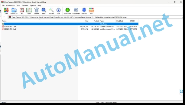
00 0288 867 1.pdf
00 0296 436 2.pdf
00 0296 436 2.pdf:
Mercedes-Benz OM906LAMercedes-Benz OM926LA
Introduction
General information
Manual validity
Using the manual
Texts and figures
Index with the structure of constructive groups
Search and find
Direction signs
Abbreviations
Technicalities
General repair instructions
Technical data
Indications for correct repair
Self-locking screws
Liquid screw insurance
Steel roller chains
connecting link
Tapered ring joints
Disassembly
Mounting
Head key joints
Disassembly
Mounting
Bearings with tension ring
Disassembly
Mounting
Bearings with tensioner sleeve
Disassembly
Mounting
Tension bushing
Disassembly
Mounting
Safety rings
Threadings with adjustment ring
Screw in
Non-tight joint with adjusting ring
Screw connections with sealing cone
Hydraulic hoses
Laying the hoses
Joint surface work
Replacement parts
Tightening torques
Tightening torques for normal metric threads
Tightening torques for metric fine threads
Tightening torques for hydraulic threads and air conditioning threads with sealing cone and O-ring DIN 3865
Tightening torques for hydraulic threads with adjusting ring DIN 3861
Tightening torques for threaded fittings of the SDS hydraulic system
Tightening torques for oscillating hydraulic threadings
Tightening torques for hollow screws DIN 7643
Tightening torques for threaded fittings of the SDE hydraulic system with adjustable direction
Tightening torques for brake line joints
Tightening torques for helical thread clamps
Tightening torques for spring-loaded helical thread clamps
CCN Explanation
CCN (CLAAS Component Number)
General indications
Electrical regulations
Hydraulic regulations
CCN (CLAAS Component Number)
Security
General information
To especially take into account
Signaling of warning and alarm indications
Rules to avoid accidents with personal injury
General indications
Check, adjustment and repair work
Engine operation
Suspended loads
Work on pipes and hoses
Work on the Common Rail system
Electrical installation work
Work in the hydraulic installation
Electric welding
lacquer work
Works on urea solution
Tips on how to avoid damage and premature wear
General indications
Limitation of liability
General indications
Immobilization and storage
Prescriptions to avoid damage to health and the environment
Prevention measures to protect against health and environmental damage
Disposal of consumables and auxiliary consumables
Instructions for working on the diesel engine
Protection against accidents
Cleaning
Assembly instructions
Engine check
Commissioning after an engine overhaul
First aid
01 Engine
0102 Complete component
Engine characteristic data
Engine Description
engine components
Power-on sequence
turn the engine
Special tool with motor mounted
Special tool with the engine removed
Turn the engine in assembled state
Turn the engine in disassembled state
0105 Engine suspension
Hooking rings
Technical instructions
0110 Engine casing
special tool
Technical instructions
Disassemble
Front crankshaft gasket
special tool
Technical instructions
Disassemble
Rear crankshaft gasket
special tool
Technical instructions
Disassemble
control box
special tool
Technical instructions
Disassemble
Oil separator
Technical instructions
0115 Engine propulsion
special tool
Technical instructions
Disassemble
Measure the overhang
Connecting rod
Technical instructions
Disassemble
Inside diameter
Technical instructions
crankshaft sprocket
special tool
Assembly instructions
Crankshaft
special tool
Technical instructions
Disassemble
Oscillation damper
Technical instructions
Assembly instructions
flywheel
special tool
Technical instructions
Disassemble
Replace the ring gear
0120 Cylinder head / valves / distributor wheel
cylinder head cover
Technical instructions
Disassemble
special tool
Technical instructions
Disassemble
special tool
Technical instructions
Assembly instructions
Check the valves
Adjust valve clearance
Disassemble
Valve springs and valve stem seals
special tool
Technical instructions
Disassemble
valve guide
Preparation for work
special tool
Technical instructions
Disassemble
Camshaft
special tool
Technical instructions
Disassemble
0125 Fuel/injection system
Combustion system
Cylinder head injection pipe
special tool
Technical instructions
Assembly instructions
Nozzle support combination
Preparation for work
special tool
Technical instructions
Disassemble
Protective cap
special tool
Technical instructions
Assembly instructions
Insertable pump
special tool
Preparation for work
Technical instructions
Disassemble
fuel pump
Technical instructions
Disassemble
fuel filter housing
Technical instructions
0130 Lubricating oil system
Lubricating oil system
Preparation for work
special tool
Clean the main oil channel
Oil injection nozzle
special tool
Technical instructions
Disassemble
oil filter housing
Technical instructions
Disassemble
Valid for type: 926.959 and 926.970
Valid for type: 926.959 and 926.970
Oil radiator
Technical instructions
Disassemble
Oil pump
Preparation for work
special tool
Technical instructions
Disassemble
Install the seal
0135 Cooling system
Cooling agent
special tool
Technical instructions
Fill out
Clean the coolant circuit
Coolant pump
Technical instructions
Disassemble
Coolant thermostat
Preparation for work
Technical instructions
Disassemble
0140 Exhaust gas system
exhaust gas elbow
Technical instructions
Disassemble
Valid for type: 926.959 and 926.970
Valid for type: 926.959 and 926.970
Exhaust gas turbocharger
special tool
Technical instructions
Disassemble
Check axial play
Check radial play
Cover nozzle
Technical instructions
Disassemble
Catalyst
Preparation for work
Technical instructions
Assembly instructions
0145 Air suction
Suction housing
Technical instructions
Assembly instructions
0150 Engine coupled parts
Starting motor
Preparation for work
Technical instructions
Disassemble
Remove the magnetic drive switch
Assemble the magnetic actuation switch
Generator
special tool
Technical instructions
Disassemble
Remove the pulley
Assemble the pulley
Generator
special tool
Technical instructions
Disassemble
Remove the pulley
Assemble the pulley
Belt tensioner for generator drive belt
Technical instructions
Assembly instructions
Air compressor
Technical instructions
Disassemble
Check the oil outlet
0155 Engine adjustment
MR/PLD control knob
Technical instructions
Assembly instructions
0165 Exhaust gas aftertreatment
Exhaust gas after-processing system
Preparation for work
special tool
Technical instructions
Check the urea solution (purity)
Control the urea solution (density)
urea heating valve
Preparation for work
special tool
Technical instructions
Disassemble
urea pump
Preparation for work
special tool
Technical instructions
Disassemble
Remove the pressure accumulator
Install the pressure accumulator
Remove the instantaneous pressure reduction valve
Install the instantaneous pressure reduction valve
Remove the suction filter
Install the suction filter
Check the set of electrical conduits
Fill the pressure accumulator
urea dosing unit
Preparation for work
special tool
Technical instructions
Assembly instructions
urea injector
John Deere Repair Technical Manual PDF
John Deere Transmission Control Unit Component Technical Manual CTM157 15JUL05
John Deere Repair Technical Manual PDF
John Deere Repair Technical Manual PDF
John Deere Repair Technical Manual PDF
John Deere Repair Technical Manual PDF
John Deere Repair Technical Manual PDF
John Deere Repair Technical Manual PDF
John Deere Diesel Engines POWERTECH 2.9 L Component Technical Manual CTM126 Spanish
New Holland Service Manual PDF
John Deere Repair Technical Manual PDF
John Deere POWERTECH E 4.5 and 6.8 L Diesel Engines TECHNICAL MANUAL 25JAN08
John Deere Repair Technical Manual PDF
John Deere Diesel Engines PowerTech 4.5L and 6.8L – Motor Base Technical Manual 07MAY08 Portuguese


