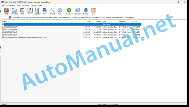
Claas Volto 1320 T 1300 T (631) Tedders Technical System EN
$300.00
- Model: Volto 1320 T 1300 T (631) Tedders
- Type Of Manual: Technical System
- Language: EN
- Format: PDF(s)
- Size: 41.8 MB
File List:
00 0290 126 0.pdf
00 0291 084 1.pdf
00 0297 467 2.pdf
00 0302 565 2.pdf
CHP-numbers for connectors CLAAS HARNESS PARTS.pdf
00 0290 126 0.pdf:
Contents
1 Introduction
Validity of the manual
Overview
2 VOLTO 52 T – Hydraulic system
Hydraulic circuit diagram up to serial no.: 407 0 2422
Circuit diagram
Key to diagram
Hydraulic circuit diagram from serial no.: 407 0 2423
Circuit diagram
Key to diagram
Windrowing rubber hydraulic circuit diagram
Circuit diagram
Key to diagram
Drawbar hydraulic cylinder (3154)
Graphics
Key to diagram
Description of function
3 VOLTO 52 T – Hydraulic system
Hydraulic circuit diagram
Circuit diagram
Key to diagram
4 VOLTO 770, 770 H – Hydraulic system
Hydraulic circuit diagram VOLTO 770
Circuit diagram
Key to diagram
Description of function
Flow divider (7069)
Key to diagram
Hydraulic circuit diagram VOLTO 770 H
Circuit diagram
Key to diagram
Description of function
Flow divider (7069)
Key to diagram
5 VOLTO 770 T – Hydraulic system
Hydraulic circuit diagram
Circuit diagram
Key to diagram
6 VOLTO 870 – Hydraulic system
Hydraulic circuit diagram up to serial no.: 1225
Circuit diagram
Key to diagram
Hydraulic circuit diagram from serial no.: 1226
Circuit diagram
Key to diagram
7 VOLTO 870 T – Hydraulic system
Hydraulic circuit diagram
Circuit diagram
Key to diagram
8 VOLTO 1050 – Hydraulic system
Hydraulic circuit diagram
Circuit diagram
Key to diagram
Description of function
9 VOLTO 1050 T – Hydraulic system
Hydraulic circuit diagram up to serial no.: 6250 1537
Circuit diagram
Key to diagram
Description of function
Working position
Description of function
Transport position
Description of function
Hydraulic circuit diagram from serial no.: 6250 1538
Circuit diagram
Key to diagram
Description of function
Working position
Description of function
Transport position
Description of function
10 VOLTO 1320 – Hydraulic system
Hydraulic circuit diagram
Circuit diagram
Key to diagram
Working position
Description of function
Transport position
Description of function
00 0291 084 1.pdf:
VOLTO 1320 T
Table of contents
Introduction
Validity of manual
Overview
CCN explanation
CCN (CLAAS Component Number)
Electric system standard
Overview
Hydraulic system standard
Overview
CCN (CLAAS Component Number)
09 Hydraulic system
0980 Hydraulic circuit diagrams
VOLTO 1320 T hydraulic circuit diagram
Working position
Description of working position function
Transport position
Description of transport position function
Position of components
Hydraulic system
Overview
00 0297 467 2.pdf:
VOLTO 1300 T
Table of contents
Introduction
Validity of manual
Overview
CCN explanation
CCN (CLAAS Component Number)
Electric systems standard
Overview
Hydraulic system standard
Overview
CCN (CLAAS Component Number)
09 Hydraulic system
0935 Hydraulic system control / monitoring
Sequence of moving from transport to working position Function: Folding-out sequence diagram
Function description
Sequence description: Folding out to working position
Designations
Sequence of working position to transport positionFunction:Folding-in sequence diagram
Function description
Description of sequence: Folding in to transport position
Sequence of headland to working positionFunction:Headland to working position sequence
Function description
Description of sequence: from headland to working position
Designations
Sequence of working to headland positionFunction:Working to headland position sequence diagram
Function description
Description of sequence: from working to headland position
Designations
0980 Hydraulic circuit diagrams
VOLTO 1300 T
VOLTO 1300 T (fully equipped) Hydraulic system: Circuit diagram (fully equipped)
Description of function: headland position (option)
VOLTO 1300 T
VOLTO 1300 T
0997 Inspecting / Measuring / Setting
Adjusting the stroke limitation valves
Adjusting dimension a
10 Electrical / Electronic equipment
1080 Electronic circuit diagram
VOLTO 1300 circuit diagram (type 631)
SCM 01 – Lighting Europe
Designations
VOLTO 1300 T circuit diagram (type 631)
SCM 02 – Lighting USA
Designations
1090 Accessories
Connector database (chp CLAAS)
Example of representation of key numbers (CHP)
Key number (CHP)
Connector representation (CHP)
Position of components
Hydraulic system
3000 Hydraulic cylinders
4000 Restrictor / orifice plate
5000 Accumulators
6000 Valves – mechanically actuated
7000 Valves, hydraulically actuated
Electric system
C Electrical / electronic devices
00 0302 565 2.pdf:
Sensor system
Table of contents
CCN explanation
CCN (CLAAS Component Number)
Electric system standard
Overview
Hydraulic system standard
Overview
CCN (CLAAS Component Number)
Introduction
Safety rules
Safety and hazard information
10 Electrical / Electronic equipment
1097 Testing / Measuring / Adjusting
Test report of the angle sensor (0011780.x)
Application of test report
Required tools
Test report of the angle sensor (0011780.x)
Testing / Measuring / Adjusting of angle sensor (0011780.x)
1. Reason for test
2. Mechanical test of angle sensor
3. Electric test with CDS
4. Electric test with multimeter
5. Mechanical test of connecting cable
Completing the machine
Test report of position and speed sensors
Application of test report
Required tools
Sensor variants
Part numbers of speed sensors
Part number of position sensor
Test report of position and speed sensors
Testing / measuring / adjusting of position and speed sensors
1. Reason for test
2. Mechanical test
3. Electric test with CDS
4a. Installation dimensions
Check of installation dimension
Installation dimensions of gearbox speed sensor (0011 799.x) and cam speed sensor (0011 810.x)
Installation dimension of position sensor (0011 815.x)
4b. Installation position
Centring of sensor
Metal-free zone
5. Electric test with multimeter
Voltage measurement
Direction of rotation and speed sensor (0011 605.x)
Measured values table
6. Mechanical test of connecting cable
Completing the machine
Test report of the urea sensor (00 0773 207 x)
Application of test report
Required tools
Parts number of the urea sensor
Test report of the urea sensor
Testing / measuring / adjusting urea sensor
1. Reason for test
2. Mechanical test
3. Mechanical test of connecting cable
4. Electric test with multimeter
5. Component test with the CDS
CHP-numbers for connectors CLAAS HARNESS PARTS.pdf:
CLAAS HARNESS PARTS
Table of contents
10 Electrical / Electronic equipment
1081 Overview of connectors
CLAAS HARNESS PARTS (CHP)
John Deere Repair Technical Manual PDF
John Deere PowerTech M 10.5 L and 12.5 L Diesel Engines COMPONENT TECHNICAL MANUAL CTM100 10MAY11
John Deere Repair Technical Manual PDF
John Deere Repair Technical Manual PDF
John Deere Repair Technical Manual PDF
John Deere Repair Technical Manual PDF
John Deere Parts Catalog PDF
John Deere Tractors 6300, 6500, and 6600 Parts Catalog CQ26564 (29SET05) Portuguese
John Deere Repair Technical Manual PDF
John Deere Parts Catalog PDF
John Deere Tractors 7500 Parts Catalog CPCQ26568 30 Jan 02 Portuguese

