Claas Volto 77 (231) Tedders Assembly Instruction EN
$50.00
- Model: Volto 77 (231) Tedders
- Type Of Manual: Assembly Instruction
- Language: EN
- Format: PDF(s)
- Size: 55.1 MB
File List:
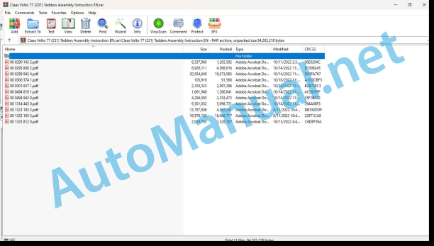
00 0290 143 2.pdf
00 0295 808 2.pdf
00 0299 942 4.pdf
00 0300 374 1.pdf
00 0301 637 1.pdf
00 0494 810 1.pdf
00 0494 942 0.pdf
00 1314 443 0.pdf
00 1323 185 3.pdf
00 1323 185 5.pdf
00 1323 812 0.pdf
00 0295 808 2.pdf:
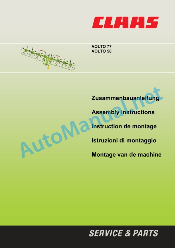
Zusammenbauanleitung
1 Einleitung
Einleitung
3 Allgemeine Hinweise
Be sure to be stranded
Kennzeichnung von Warn- und Gefahrenhinweisen
Bestimmungsgemäße Verwendung
Safety precautions with warning notice
Allgemeine Sicherheitshinweise
4 Montagehinweise
General information regarding installation
Zusammenbau des Wirbelwenders
5. Work Follow
VOLTO 77 5.3
VOLTO 58 5.17
For participation:
Assembly instructions
1 Introduction
Introduction
2 Contents
3 General Information
Of special importance
Identification of warnings and dangers
Designated use
Safety decals with warning symbols
General safety instructions
4 Assembly instructions
General instructions for assembly
Assembly of the Rory tedder.Work sequence
VOLTO 77 5.3
VOLTO 58 5.17
Before operation
Assembly instructions
1 Introduction
Introduction
2 Table des matières
3 General Conseils
Important
Identification of the prescriptions concerning the avertissements and the dangers
Utilization conforme à l’usage prévu
Etiquette de sécurité avec pictogramme de danger
Consignes de sécurité generales
4 Consignments for assembly
Consignes generales pour le montage
Mounting the Faneuse tourbillon
5. Ordre des opérations
VOLTO 77 5.3
VOLTO 58 5.17
Avant la mise en service :
Istruzioni di montaggio
1 Introduction
Introduzione
3 Indicazioni generali
Avvertenze importanti
Simbologia concernente gli avvertimenti and gli avvisi di pericolo
Norme per il corretto impiego
Decalcomania con simboli di pericolo
Indicazioni generali per la sicurezza
4 Indicazioni per il montaggio
Indicazioni generali per il montaggio
Montaggio dell’Voltafieno rotativo
5. Sequenza di lavoro
VOLTO 77 5.3
Primaessa en esercizio:
Assembly instructions
1 Introduction
Introduction
2 Table of contents
3 General instructions
What you should pay particular attention to
Indication of warnings and dangers
Use according to intended use
Safety stickers with hazard symbols
General safety instructions
4 Assembly instructions
General instructions for installation
Assembly of the Circle Shaker
5. Work sequence
VOLTO 77 5.3
VOLTO 58 5.17
Before commissioning
Arbeitsfollow
Work sequence
Order of Operations
Sequenza di lavoro
Work order
VOLTO 77
VOLTO 77
VOLTO 58
VOLTO 58
00 0299 942 4.pdf:
Montageanleitung
Assembly instructions
Notice de montage
Installation instructions
Istruzioni di montaje
Installation management
Assembly instructions
Installation manual
Installation instructions
Montagehandleiding
Mounting instructions
Montagenvisning
Montingsveiling
Installations
Paigaldusjuhend
Assembly instructions
Let’s install the instructions
Instrucs
Installation instructions
Ably instructions
00 0494 942 0.pdf:
Anbauanleitung
Hydraulic Begrenzungstuch
1 Instructions
Instructions
2 Inhalt
3 Allgemeine Hinweise
Besons on the beach
Kennzeichnung von Warn- und Gefahrenhinweisen
Sicherheitaveckleber mit Warnbildzeichen
Bestimmungsgemäße Verwendung
4 Anbau Begrenzungstuch
Allgemeine Hinweise zur Montage
Hydraulic installation Begrenzungstuch
Hydraulic valve
Hydraulik plan
Schlauchverlegung
Traktoranschluss
Einstellung Begrenzungstuch
You can open the doors and the beaches!
Fitting instructions
Hydraulic windrowing rubber
1 Introduction
Introduction
2 Table of contents
3 General instructions
Of special importance
Identification of warnings and dangers
Safety decals with warning symbols
Designated use
4 Installation of windrowing rubber
General instructions for installation
Assembly of the hydraulic windwing rubber
Hydraulic connection
Hydraulic layout
Hose layout
Tractor connection
Adjusting windrowing rubber
Check and observe the following before putting into operation!
Installation instructions
Hydraulic spreading limitation canvas
1 Introduction
Introduction
2 Table of contents
3 General instructions
Important
Identification of warning and hazard requirements
Safety labels with danger pictograms
Use as intended
4 Mounting the spreading limitation fabric
General assembly notes
Installation of the hydraulic spreading limitation fabric
Hydraulic connection
Hydraulic plan
Laying the pipe
Connecting the trailer
Adjusting the spreading limitation fabric
To be checked and taken into account before commissioning!
Mountain structure
Anti-propelled valve with hydraulic control
1 Introduction
Introduction
3 General instructions
Important warnings
Symbols concern warnings and warnings of pericolo
Decal with symbols concerning security
Norm per il corretto impiego
4 Anti-protection button
General instructions for the mountain
Anti-propelled switch with hydraulic control
Hydraulic connection
Hydraulic diagram
Installation of the flexible tube
Collegamento al trattore
Registration of anti-protection details
First of all, please check and verify!
Lieferumfang
Package list
Parts supplied
Complete furnishings
Kit: 00 0494 938 0
Arbeitsfolge
Procedure
Sequence of work
Procedure
00 1314 443 0.pdf:
Vorgewende-Aushebung
1 Safety
1.1 Besonders zu beachten
1.2 Bestimmunggemäße Verwendung
1.3 Allgemeine Sicherheitshinweise
1.4 Warnbildzeichen
1.4.1 Warning symbols
1 Safety
1.1 Of special importance
1.2 Intended use
1.3 General safety instructions
1.4 Safety decals
1 Security
1.1 Important
1.2 Conformity of use
1.3 General safety instructions 1.4 Warning pictogram
1 Security
1.1 Important notice
1.2 Standard for the correct employment
1.3 General indications for safety
1.4 Decalcomanie con symboli di pericolo
1 Security
1.1 To be observed in particular
1.2 Use in accordance with the rules provided
1.3 General safety instructions
1.4 Safety sticker with warning symbol
1 General guidelines
1.1 What you should pay special attention to
1.2 Application as intended
1.3 General safety instructions
1.4 Stickers with warning signs and symbols
00 0494 830 0
00 0494 830 0
00 1323 185 3.pdf:
Allgemeine Hinweise
Sicherheitshinweise
Handhandung der Anleitung
Symbole Warnhinweise
General instructions
Safety precautions
Handling of manual
Symbols and warnings
General remarks
Security advice
Use of the notice
Warning symbols
General warning
Safety standard
Use of the Instruction Manual
Danger warning symbol
General indications
Security measures
Use of the instruction manual
Symbols of the warning indications
General instructions
Safety instructions
Пользование Руководством
Warning symbols
LINER 4000
LINER 3500
LINER 1750 / 1650 TWIN
LINER 1250 Profile
LINER 3100
LINER 2900 / 2800 / 2700 / 2600
LINER 750 TWIN / 650 TWIN
VOLTO 1320 T
VOLTO 1320 T
VOLTO 1100T / 900T
VOLTO 1100 T / 900 T / 800 T
VOLTO 1100 / 900
VOLTO 1100 / 900 / 800 / 700
VOLTO 77 / 58
VOLTO 75 T / 750
VOLTO 64 / 640 H / 640 HR
VOLTO 52 T
VOLTO 52 / 45
00 1323 812 0.pdf:
Vorgewende-Aushebung
1 Safety
1.1 Besonders zu beachten
1.2 Bestimmunggemäße Verwendung
1.3 Allgemeine Sicherheitshinweise
1.4 Warnbildzeichen
1.4.1 Warning symbols
1 Safety
1.1 Of special importance
1.2 Intended use
1.3 General safety instructions
1.4 Safety decals
1 Security
1.1 Important
1.2 Conformity of use
1.3 General safety instructions
1.4 Warning pictogram
1 Security
1.1 Important nthe correct employment
1.3 General indications for safety
boli di pericolo
1 Security
1.1 To be observed in particular
1.2 Use in accordance with the rules provided
1.3 General safety instructions
1.4 Safety sticker with warning symbol
1 General guidelines
1.1 What you should pay special attention to
1.2 Application as intended
1.3 General safety instructions
1.4 Stickers with warning signs and symbols
00 0494 830 0
00 0494 830 0
John Deere Parts Catalog PDF
John Deere Tractors 6300, 6500, and 6600 Parts Catalog CQ26564 (29SET05) Portuguese
John Deere Repair Technical Manual PDF
John Deere Repair Technical Manual PDF
John Deere Repair Technical Manual PDF
John Deere Repair Technical Manual PDF
John Deere Repair Technical Manual PDF
John Deere PowerTech M 10.5 L and 12.5 L Diesel Engines COMPONENT TECHNICAL MANUAL CTM100 10MAY11
John Deere Repair Technical Manual PDF
John Deere Repair Technical Manual PDF

