Claas Xerion 3000-2500 (033) Tractors Technical System EN
$300.00
- Model: Xerion 3000-2500 (033) Tractors
- Type Of Manual: Technical System
- Language: EN
- Format: PDF(s)
- Size: 31.1 MB
File List:
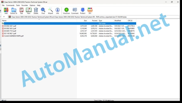
00 0302 343 1.pdf
00 0302 565 2.pdf
00 0305 772 0.pdf
00 1143 962 1.pdf
CLAAS HARNESS PARTS.pdf
00 0302 343 1.pdf:
PROFI CAM 3
Table of contents
General information
Marking of warnings and hazard prevention notes
First-aid measures
CCN explanation
CCN (CLAAS Component Number)
Electric system standard
Overview
Hydraulic system standard
Overview
CCN (CLAAS Component Number)
10 Electrical / Electronic equipment
1030 Board computer / Indicators
Camera system
Description of function
1097 Testing / Measuring / Adjusting
Testing / measuring / adjusting the PROFI CAM
Checking the fuse in the video channel select box (C102)
Testing the video camera connector (C055)
1098 Fault / remedy
Fault / remedy PROFI CAM
The video monitor (C101) shows no image or cannot be switched on (indicator light fails to light up)
Video monitor (C102) displays a blue image either permanently or temporarily
The video monitor image is blurred
Replacing the fuse in the video channel select box (C102)
Connection and connecting cable with video camera (C055)
00 0302 565 2.pdf:
Sensor system
Table of contents
CCN explanation
CCN (CLAAS Component Number)
Electric system standard
Overview
Hydraulic system standard
Overview
CCN (CLAAS Component Number)
Introduction
Safety rules
Safety and hazard information
10 Electrical / Electronic equipment
1097 Testing / Measuring / Adjusting
Test report of the angle sensor (0011780.x)
Application of test report
Required tools
Test report of the angle sensor (0011780.x)
Testing / Measuring / Adjusting of angle sensor (0011780.x)
1. Reason for test
2. Mechanical test of angle sensor
3. Electric test with CDS
4. Electric test with multimeter
5. Mechanical test of connecting cable
Completing the machine
Test report of position and speed sensors
Application of test report
Required tools
Sensor variants
Part numbers of speed sensors
Part number of position sensor
Test report of position and speed sensors
Testing / measuring / adjusting of position and speed sensors
1. Reason for test
2. Mechanical test
3. Electric test with CDS
4a. Installation dimensions
Check of installation dimension
Installation dimensions of gearbox speed sensor (0011 799.x) and cam speed sensor (0011 810.x)
Installation dimension of position sensor (0011 815.x)
4b. Installation position
Centring of sensor
Metal-free zone
5. Electric test with multimeter
Voltage measurement
Direction of rotation and speed sensor (0011 605.x)
Measured values table
6. Mechanical test of connecting cable
Completing the machine
Test report of the urea sensor (00 0773 207 x)
Application of test report
Required tools
Parts number of the urea sensor
Test report of the urea sensor
Testing / measuring / adjusting urea sensor
1. Reason for test
2. Mechanical test
3. Mechanical test of connecting cable
4. Electric test with multimeter
5. Component test with the CDS
00 0305 772 0.pdf:
Table of contents
Introduction
Notes on the manual
Information about this Technical Systems Manual
Using the manual
Document structure based on subassemblies
Search and find
Directions
Identifying warnings
Hazard signs
Signal word
Safety rules
Safety signs and warnings
Requirement made on technical staff
Children in danger
Hazard areas of the machine
Instructors travelling along during fieldwork
Risk of injury from rotating shafts
Structural alterations of the machine
Optional equipment and spare parts
Control of running machine
Technical condition
Respecting technical limit values
Danger from machine parts that continue rotating
Keeping safety devices functional
Personal protective equipment
Wearing suitable clothing
Removing dirt and loose objects
Parking the machine safely
Unsuitable operating utilities
Safe handling of service fluids and auxiliary utilities
Environmental protection and disposal
Keeping the cab free of chemicals
Avoiding fires
Potentially fatal electric shock from overhead lines and lightning strike
Electric shock from electric system
Noise may damage your health
Pre-loaded machine parts
Liquids under pressure
Compressed air
Toxic exhaust gases
Hot surfaces
Safe access and leaving
Working only on the stopped machine
Hazards during repairs
Raised machine parts and loads
Danger from welding work
Checking and charging the battery
Preparations for cases of emergency
10 Electrical / Electronic equipment
1098 Fault / remedy
ISOBUS checklist for fault analysis
Use of the checklist
1. Fault when loading the graphical user interface of the ISOBUS implement
1.1 The graphical user interface for an ISOBUS implement (object pool) is not loaded to the terminal
1.2 Loading the graphical user interface of the ISOBUS implement is not finished or is interrupted
1.3 The graphical user interface for an ISOBUS implement is loaded to the wrong terminal
2. Fault when assigning function keys
2.1 No keys available for assigning, no AUX input available
2.2 Assigned function keys without a function or faulty
2.3 Assignment of function keys after restarting no longer available
3. Task management fault (TC BAS)
3.1 Meter readings from the implement not available or remain at zero
3.2 Import/export of iso.xml not possible/only partially possible
3.3 Missing reference tracks in import/export
3.4 Individual tasks cannot be deleted from the terminal
3.5 Folder structure task data on the USB stick
4. Section Control fault (TC SC)
4.1 TC SC at the wrong terminal
4.2 TC SC without a function/only with a partial function
4.3 Incorrect switching on or off of TC SC
5. Testing and measuring
5.1 Testing and measuring – terminal socket
5.2 Testing and measuring – ISOBUS socket
5.3 Testing and measuring – diagnostic socket
6. Diagnosis with CDS
6.1 ISOBUS check (load object pool)
6.2 ISOBUS CAN logging (assigning of function keys)
6.3 ISOBUS CAN logging (assigned key without a function)
6.4 ISOBUS CAN logging (assignment no longer available, gets lost)
6.5 ISOBUS CAN logging (in the event of a fault with task management)
6.6 ISOBUS CAN logging (general problems)
7. ISOBUS components/AEF compatibility/software statuses
7.1 ISOBUS components and fault description
7.2 ISOBUS functionalities
7.3 Software statuses/AEF compatibility
00 1143 962 1.pdf:
FL – FLC – FLE loaders
Table of contents
CCN explanation
CCN (CLAAS Component Number)
Electric system standard
Overview
Hydraulic system standard
Overview
CCN (CLAAS Component Number)
Introduction
General information
Using this diagnostic manual
Safety rules
Safety instructions and risk information
Validity of manual
Validity of this diagnostic manual
06 Lift device
0615 Front loader
Reminder
Control valve slide valves
Lifting circuit
“Shock Eliminator System” (Option)
Loading circuit
Loading circuit of FL loaders
Loading circuit of FLC – FLE loaders
Parallelogram hydraulic circuit
Hydraulic parallelogram – “PCH System”
3rd function circuit
Loading retarder
4th function circuafety system circuit
“ACS” circuit
“SCS” circuit
“Fast-Lock System” circuit
“Speed-Link System” circuit
Mechanical part
0698 Problems / remedy
Faults on the Mach System
Appeaaults on Flexpilot System
Open centre: Hydraulic malfunction noted on the tractor
Open centre: Loader does not lift the load stated
Load sensing signal (LS): Hydraulic malfunction noted on the tractor
Load sensing signal: Loader does not lift the load stated
Faults on Flexpilot System
Appearance of jerking relating to the hydraulic system
Abnormally hard to move the control lever
Control valve body rupturing under the effect of the pressure as soon as the vehicle is first switched on
Response time too long
Appearance of oil leaks outside the control valve
Faults on lifting circuit
Loader lowering by itself
Faults on loading circuit
Loader dumping by itself
Lack of power when digging orhecking the loader solenoid valves
Characteristics of the solenoid valves
Solenoid valve not working
Dismantling the solenoid valve
Dismantling the solenoid valve of the 3rd function on the FL loader
User advice in order to avoid clogging the solenoid valves
10 Electrical / Electronic equipment
1015 Wiring harnesses
Overview of the FL loader wiring harnesses
Wiring harness for loader equipped with 3rd function
Wiring harness for loader equipped with 3rd function and 4th function
Wiring harness for loader equipped with 3rd function, 4th function, ACS and “Fast-Lock” or “Speed-Link”
Wiring harness for loader equipped with 3rd function, 4th function, SCS, ACS and “Fast-Lock” or “Speed-Link”
Wiring harness for safety loader on the lifting and loading circuit
Overview of the FLC loader wiring harnesses
Wiring harness for loader equipped with 3rd function
Wiring harness for loader equipped with 3rd function and 4th funct harness for loader equipped with 3rd function, 4th function, and “Fast-Lock”
Wiring harness for loader equipped with safety function on lifting and loading
Overview of FLE loader wiring harnesses
Wiring harness for loader equipn
Wiring harness for loader equipped with safety function on lifting and loading
Position of components
Hydraulic system
3000 Hydraulic cylinders
5000 Accumulators
8000 Couplings – Connections
Electric system
V Electronic components
X Connections
Y Electromagnetic coil
CLAAS HARNESS PARTS.pdf:
CLAAS HARNESS PARTS
Table of contents
10 Electrical / Electronic equipment
1081 Overview of connectors
CLAAS HARNESS PARTS (CHP)
John Deere Repair Technical Manual PDF
John Deere Repair Technical Manual PDF
John Deere Transmission Control Unit Component Technical Manual CTM157 15JUL05
John Deere Parts Catalog PDF
John Deere Harvesters 8500 and 8700 Parts Catalog CPCQ24910 Spanish
John Deere Repair Technical Manual PDF
John Deere Repair Technical Manual PDF
John Deere Parts Catalog PDF
John Deere Tractors 6300, 6500, and 6600 Parts Catalog CQ26564 (29SET05) Portuguese
John Deere Repair Technical Manual PDF
John Deere 16, 18, 20 and 24HP Onan Engines Component Technical Manual CTM2 (19APR90)
John Deere Repair Technical Manual PDF
John Deere Repair Technical Manual PDF

