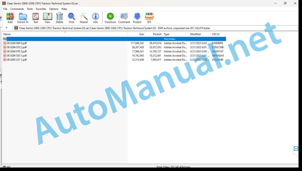
Claas Xerion 3800-3300 (781) Tractors Technical System ES
$300.00
- Model: Xerion 3800-3300 (781) Tractors
- Type Of Manual: Technical System
- Language: ES
- Format: PDF(s)
- Size: 119 MB
File List:
00 0290 069 0.pdf
00 0294 070 2.pdf
00 0294 076 3.pdf
00 0294 353 1.pdf
00 0295 257 1.pdf
00 0290 069 0.pdf:
XERION 3800 TRAC / TRAC VCXERION 3300 TRAC / TRAC VCa from machine 781 00110
CCN Explanation
CCN (CLAAS Component Number)
General indications
Electrical regulations
Hydraulic regulations
CCN (CLAAS Component Number)
Introduction
Safety instructions
Safety measures and danger notices
Manual validity
01 Engine
0135 Cooling system
Engine cooling (reversing fan)
Tables of measured values
Function Description
Thermometer element with elastomer piece
0150 Engine coupled parts
Main voltage supply, starter motor
Function Description
Diagnostic chart
Occupation of the sockets
Connection List
Starting the diesel engine, adjusting the diesel engine speed
With diesel engine with TIER 3 exhaust gas regulations (ACERT)
Function Description
Electronic acceleration change logic
Diagnostic chart
Occupation of the sockets
Connection List
0155 Engine adjustment
Diesel engine control
Function Description
Table of measured values
Diagnostic chart
Occupation of the sockets
Connection List
02 Gears / clutch / cardan shaft
0238 Gearbox control/drive
Gearbox control
Function Description
Table of measured values
Diagnostic chart
Occupation of the sockets
Connection List
Clean Home
Function Description
Diagnostic chart
Occupation of the sockets
Connection List
0242 Differential
Lock differentials
Function Description
Table of measured values
Diagnostic chart
Occupation of the sockets
Connection List
03 Chassis
0310 Axle
Lock the rotary axis
Function Description
Table of measured values
Table of measured values of the hydrc installation
Diagnostic chart
Occupation of the sockets
Connection List
0335 Propulsion
Driving management
Function Description
Table of measured values
Diagnostic chart
Occupation of the sockets
Connection List
04 Brake
0405 Service brake
Service brake (up to 78100959)
Function Description
Adjusting the brake actuation after repair work
Table of measured values
Table of measured values of the hydraulic brake installation
Diagnostic chart
Hydraulic components of the brake system (Bosch Rexroth)
Occupation of the sockets
Connection List
Service brake (from 78100960)
Table of measured values
Function Description
Charge the brake accumulator
Denomination
Function Description
Check and measure
Check max pressure of brakes
Hydraulic componthe brake system (Safim)
0415 Parking brake
Parking break
Function Description
0420 Trailer aiake equipment
Pneumatic Trailer Brake
Connection diagram for 1-duct equipment
Denominations
Markings of the connections of the parts
Connection diagram for 2-conduit equipment
Denominations
Markings of the connections of the parts
Location of components. Pneumatic Trailer Brake
0425 Hydraulic Trailer Brake
Trailer brake, central lubrication
Function Description
Table of measured values
Diagnostic chart
Occupation of the sockets
Connection List
05 Address
0505 Address
Basic information about the steering system
System concept
Orbitrol-directed rotary axis
Cab in center position: Standard steering 1, steering with the gear lever, small dog step, four-wheel steering
Denominations
Function Description
Orbitrol-steered fixed axis
Standard steering 2, joystick steering, small dog step, four-wheel steering
Denominations
Function Description
Electronic steering mode (Steer by wire)
Fully electronic steering mode, conservative gear, large dog step, synchronized steering
Denominations
Function Description
Emergency steering mode
Emergency steering mode
Denominations
Function Description
Table of measured values of the steering hydraulic system
0510 Automatic steering
AUTOPILOT
Function Description
Table of measured values
Logic table: Control of emergency steering pumps
Logic table: Cab position recognition
Diagnostic chart 28
Occupation of the sockets
Connection List
06 Lifting device
0605 Rear linkage
Three point linkage
Function Description
Diagnostic chart
Occupation of the sockets
Connection List
Rear hydraulic installation
A52 Multifunctional control module
Function Description
Table of measured values
Basic adjunt of rear linkage position sensor (B139-2)
Diagnostic chart
Occupation of the sockets
ConnectList
rotary elevator
Function Description
Front of
Function Description
Table of measured values
0610 Front linkage
Front hydraulic installation
A52 Multifunctional control module
Function Description
Table of measured values
Basic sensor adjustment (B139-1)
Diagnostic chart
Occupation of the sockets
Connection List
08 Drives
0802 Rear PTO
Switching rear power take-off
Function Description
Table of measured values
Logic table: Rear PTO, switch S114 (inside cab)
Logic table: PTO rear, switch U30 (external, fender)
Diagnostic table 7
Occupation of the sockets
Connection List
Switching the rear power take-off (automation)
Table of measured values
Function Description
Diagnostic table 15
Occupation of the sockets
Connection List
0809 Hydraulic installation drive
Secondary power take-off – Power hydraulic installation
Function Description
Table of measured values
Logic table: secondary power take-off PTO2 switch S113
Diagnostic chart
Occupation of the sockets
Connection List
09 Hydraulic
0900 General instructions for the hydraulic installation
Road traffic switching, constant pressure switching
Function Description
Table of measured values
Diagnostic chart
Occupation of the sockets
Connection List
Hydraulic installation – check and measure
Table of measured values of pumps
Table of measured values of the working hydraulic system
Table of measured values of the steering hydraulic system
Table of measured values of the hydraulic brake installation
Table of measured values of the performance hydraulic system – additional hydraulic system
0910 Bombs
PFC (Pressure Flow Controlled) Pump
Compenenominations
Function Description
Information on the PFC pump figure
Home position (motor OFF)
Function Description
Low availability
Denominations
Function Description
The pump is placed in transport
Denominations
Function Description
Constant flow
Denominations
Function Description
Regulate downwards
Denominations
Function Description
Maximum pressure limitation (DBV function)
Denominations
Function Description
0920 Valves
Steering valve block
Steering valve block
Denominations
Main valve block
Denominations
EHM 18 control unit
Denominations
Function – neutral
Function Description
Function – floating position
Function Description
Function – actuation of a consumer (increase in pressure at B)
Function Description
Three-point linkage valve block
Denominations
Valve block turn lifter
Denominations
Cab valve block (from 78100110)
Denominations
Cab valve block (from 78100428)
Denominations
Cab valve block (from 78101359)
Denominations
Brake valve (up to 78100959)
Denominations
Brake valve (from 78100960)
Denominations
Quick couplings front, rear (from 78100110)
Denominations
Additional hydraulic distributors
Function Description
Table of measured values
Table of measured values of the hydraulic installation
Diagnostic chart
Occupation of the sockets
Connection List
Blue additional hydraulic control
Function Description
Table of measured values
Diagnostic chart
Occupation of the sockets
Connection List
0930 Cylinder
Hydraulic cylinder rotate elevator
Denominations
0935 Hydraulic system control/supervision
Machine control (hydraulic installation)
Function Description
Table of measured values
Diagnostic char Occupation of the sockets
Connection List
0940 Hydraulic Performance Installation
Performance Hydraulic Installation – Aional Hydraulic System
Function Description
Technical data of the additional hydraulic pump (227)
Outlet valve flow rate – feed pump at different engine speeds
Table of measured values of the performance hydraulic system – additional hydraulic system
Multifunctional valve A (7001) and B (7002)
Function Description
0980 Hydraulic connection diagram
Global hydraulic installation connection diagram (up to 78100959)
Denominations
Global hydraulic installation connection diagram (from 78100960)
Denominations
Working hydraulic system
Connection diagram of the working hydraulic system from machine 78100110
Denominations
Hydraulic steering system
Steering valve VI
Denominations
Connection diagram of the hydraulic brake installation to machine no. 78100959
Denominations
ake hydraulic system connection diagram (from 78100960)
Connection diagram of the hydraulic system of the ECCOM 3.5 gearbox
Denomions
Performance Hydraulic Installation – Additional Hydraulic System
Performance Hydraulic Installation – Additional Hydraulic System
Denominations
Function Description
Multifunctional valve A (7001) and B (7002)
Function Description
Hydraulic cab installation (from 78100110)
Denominations
Hydraulic cab installation (from 78100428)
Denominations
Hydraulic cab installation (from 78101359)
Denominations
10 Install. electrical/electronic
1005 Power supply
ISO signal female plug
Function Description
Diagnostic chart
Occupation of the sockets
Connection List
Connection of coupled devices
Function Description
Occupation of the sockets
Connection List
Additional sockets
Occupation of the sockets
Connection List
1010 Central electrical system
Central electrical system from machine no. 78100322
Electronic components
1012 Modules / sensors
Representation of modules
Summary 1
Summary 2
Summary 3
Module A6 – Air conditioning automation (ACM)
Module A7 – Cabin Fan (CFC)
Module A9 – AUTO PILOT (ATP)
Denominations
Module A15 – Engine control module (ECM) – CATERPILLAR (CAT C9)
Module A30 – CEBIS Terminal
Module A33 – Sidefinder – Pathfinder
Module A55 – Electrohydraulic steering plug 1 (EHL)
Module A055 – Electrohydraulic steering plug 2 (EHL)
Module A56 – VDC (Vehicle drive control)
Gear shift control module (TCU)
Module A58 – Hydraulic lift regulation (EHR)
A59-1 valve timing module (VCU)
A59-2 valve timing module (VCU)
Module A60 – hydraulic control (HYD)
Module A61 – XERION on-board informant (XIF)
Module A61 – XERION on-board information (XIF) – rear power take-off switching (automation)
Module A62 – external control (EXT)
A66 Module – GPS PILOT (GPM)
Module A70 – power hydraulic installation (PHM)
1020 Advance lighting
Rotating flashing light
Occupation of the sockets
Connection List
Flashing light equipment Europe
Function Description
Diagnostic chart
Occupation of the sockets
Connection List
Flashing lights equipment (USA)
Function Description
Diagnostic chart
Occupation of the sockets
Connection List
Rear light, position light
Occupation of the sockets
Connection List
Low beam, high beam
Occupation of the sockets
Connection List
Brake light, reversing lights
Diagnostic chart
Occupation of the sockets
Connection List
1025 Work lighting
Work lighting I
Diagnostic chart
Occupation of the sockets
Connection List
Work lighting
Function Description
Occupation of the sockets
Connection List
1030 On-board computer / display devices
ISO terminal, ISO handling
Function Description
Diagnostic chart
Connection List
1035 Multifunctional handle/lever
External handling (EXT module)
Function Description
Diagnostic chart
Occupation of the sockets
Programmable functions (F keys)
A52 Multifunctional control module
Function Description
Diagnostic chart
Occupation of the sockets
Connection List
1080 Electronic connection diagram
01a Main voltage supply, diesel engine starter motor
Denominations
02a Start the diesel engine, adjust the diesel engine speed
Denominations
03a Diesel engine control
Denominations
04a Road traffic switching, constant pressure switching
Denominations
Denominations
05a Terminal
Denominations
06a CAN-Bus, module voltage supply
Denominations
07a Switching the rear power take-off
Denominations
08a Secondary power take-off – power hydraulic installation
Denominations
09a External operation (EXT module)
Denominations
10a ISO Terminal, ISO handling
Denominations
Denominations
11a ISO signal female plug
Denominations
12a Programmable functions (F keys)
Denominations
13a Connection of coupled devices
Denominations
14a Three-point linkage
Denominations
15a Switching the rear power take-off (automatic)
Denominations
20a Front hydraulic installation
Denominations
21a EHR rear hydraulic installation
Denominations
22a Service valves, additional control devices
Denominations
23a Blue service valve
Denominations
26a Machine control (hydraulic installation)
Denominations
Denominations
28th EHL (AUTO PILOT), cockpit position recognition
Denominations
30a Omnidirectional light
Denominations
31a Lock the rotating axis
Denominations
32a Lock the differentials
Denominations
33a Turn the cabin
Denominations
36th Europe Flashing Team
Denominations
36b Flashing lights equipment (USA)
Denominations
37a Windshield wipers, windshield wiper equipment
Denominations
38a Automatic air conditioning system
Denominations
39a Operator’s seat
Denominations
40a Additional sockets
Denominations
41a Advance control, brake, parking brakes
Denominations
42a Clean Home
Denominations
43a Trailer brake, central lubrication system
Denominations
44a Gearbox control
Denominations
45a Switching main light, rear light, position light
Denominations
46a Low beam, high beam, headlight switching
Denominations
47a Working lighting I
Denominations
48a Work lighting II
Denominations
49a Horn, brake light, reversing lights
Denominations
50a Instrument lighting, radio, mirror adjustment
Denominations
1085 Networks
CAN-Bus system with GPS PILOT II
Function Description
Function Description
Table of measured values 250 kB vehicle CAN-Bus (Vehicle CAN-Bus)
Table of measured values 250 kB CAN-Bus hydraulic system
Table of measured values J1939 CAN-Bus
Table of measured values ISO 11783 CAN-Bus
Occupation of the sockets
Connection List
1090 Accessories
Socket database (chp CLAAS)
12 Driver 1210 Cabin
Turn the cabin
Function Description
Table of measured values
Cabin latch sensor (B147)
Diagnostic chartmeasured values of the hydraulic installation
Occupation of the sockets
Connection List
Windshield wipers, windshield wiper equipment
Occupation of the sockets
Connection List
1225 Mirror
Mirror adjustment, instrument lighting
Occupation of the sockets
Connection List
1230 Seat
Driver’s seat
Function Description
Occupation of the sockets
Connection List
1240 Air conditioning equipment
Automatic air conditioning system
Function Description
Table of measured values
Test menu:
Test menu management
Occupation of the sockets
Connection List
92 Diagnosis
9210 Machine Error Codes
FMI error code (Failure Mode Indicator)
General indications
FMI 00 (signal too large)
FMI 01 (signal too small)
IMF 02 (implausible sign FMI 03 (voltage too high)
FMI 04 (voltage too low)
FMI 05 (current too low)
FMI 06 (current too high)
FMI 07 (mechanical error)
FMI 08 (defective frequency signal)
IMF 09 (communication error)
FMI 10 (signal change too fast)
IMF 11 (multiple error)
FMI 12 (defective ECU)
FMI 13 (signal outside calibration range)
IMF 16 (non-existent parameter)
FMI 17 (ECU not responding)
FMI 18 (power supply error)
FMI 19 (software requirements not met)
IMF 95 (no signal change)
FMI 96 (CAN-Bus system defective)
IMF 97 (implausible state)
IMF 98 (warning)
IMF 99 (info)
XERION error codes (type 781)
DTC (Diagnostic Trouble Code) Summary
9220 Diesel Engine Error Codes (J1939)
Diesel Engine Error Codes – J 1939 / Engine Diagnosis / Parts Location
Function Description
CATERPILLAR C9 (TIER3)
Error code MB, CAT TIER 3 and 4
Location of components
Electrical installation
To Terminal/modules
B Sensors
and lighting
G Voltage sources
H Signaling device / light signal
M Motor (electric)
R Potentiometer/resistance
S Switch/button – cabin operation
U Switch – external operation
and electromagnetic coils
Z Effective value switch
Hydraulic installation
1000 Oil tank / oil filter / oil radiator
2000 Pump/motor
3000 Hydraulic Cylinders
4000 Restrictor / calibrated orifice
5000 Pressure accumulator
6000 Valves – mechanically actuated
7000 Valves – hydraulically actuated
8000 Couplings/connections
9000 Measuring points / indicating instruments
Component grid – electrical installation – location of components
00 0294 070 2.pdf:
1 Global hydraulic system
Hydraulic connection diagram up to nr. 78100109
Global wiring diagram
Denominations
Hydraulic connection diagram from nr. 78100110
Global wiring diagram
Denominations
PFC pump – compensation valve
Denominations
Function Description
PFC pump – output position (motor OFF)
Denominations
Function Description
PFC pump – low reserve
Denominations
Function Description
PFC pump – pump is placed on feed
Denominations
Function Description
PFC pump – constant volumetric flow
Denominations
Function Description
PFC pump – regulate down
Denominations
Function Description
PFC pump – maximum pressure limitation (pressure limitation valve function)
Denominations
Function Description
2 Hydraulic steering system
System concept
Description
Emergency steering operation
Hydraulic connection diagram
Denominations
Function
Standard steering 1 (Orbitrol steered oscillating axle)
Hydraulic connection diagram
Denominations
Function
Standard steering 2 (fixed axle steered by Orbitrol)
Hydraulic connection diagram
Denominations
Function
Fully electronic steering operation (Steer by wire)
Hydraulic connection diagram
Denominations
Function
Steering valve VI
Denominations
3 Hydraulic operating system
Hydraulic connection diagram up to nr. 78100109
Connection diagram of the operating hydraulic system
Denominations
Hydraulic connection diagram from nr. 78100110
Connection diagram of the operating hydraulic system
Denominations
Main valve block
Denominations
EHM18 control unit
Denominations
Neutral function
Floating position function
Function: activation of a consumer (increase in pressure at B)
Three-point braces
Denominations
Rotate the lift – hydraulic valve
Denominations
Denominations
Cab valve block (II) – up to machine no. 109
Denominations
Function Description
Cab valve block (II) – from machine no. 110
Denominations
Rotate lift – hydraulic cylinder
Turn the cab, raise/lower the cab – starting from machine no. 110
Denominations
Quick couplings front, rear – up to machine no. 109
Denominations
Quick couplings front, rear – from machine no. 110
Denominations
4 Hydraulic brake installation
Hydraulic connection diagram
Connection diagram of the hydraulic brake installation
Denominations
Description
Adjust the brake operation after repair work.
Main brake valve VII
Denominations
Location of components – pressure accumulator
5 Compressed air installation
1- & 2-pipe installation, 2-pipe installation
Connection diagram for 1- & 2-pipe installation
Denominations
Component connection designations
Connection diagram, 2-pipe installation
Denominations
Component connection designations
Location of components
6 Additional hydraulic system
Hydraulic connection diagram
Additional hydraulic system connection diagram
Denominations
Components
Description
Multifunctional valve A (7001)Multifunctional valve B (7002)
7 Check and measure
Tables of measured values
Table of measured values of pumps
Table of measured values of the operating hydraulic system
Table of measured values of the steering hydraulic system
Table of measured values of the hydraulic brake installation
Table of measured values of the additional hydraulic system
8 Location of components
Main construction units (I to XI)
Individual components of the main valve block (I)
Individual components valve block from cab (II) to machine no. 78100109
Individual components cab valve block (II) from machine no. 78100110
Individual components of the distribution block (III)
Individual componenIV) steering valve
Individual direction valve components (V)
Individual components of the EHL valve block – electrohydraulic steering (VI)
Individual components of the main brake valve (VII)
Individual components of the operating hydraulic system adjustment pump (VIIIponents of the steering hydraulic system adjustment pump (IX)
Individual three-point brace components (X)
Individual components turn the elevator (XI)
Other individual components
Alphabetical index
00 0294 076 3.pdf:
1. Introduction
Structure of the electrical installation documentation
Connection diagram
Coordinates on the grid
Connection List
CLAAS standardization:
2 Basic knowledge of electrical installation
Resistance measurement
Denominations
Function Description
Voltage measurement
Denominations
Function Description
Current measurement
Denominations
Function Description
3 Basic knowledge of hydraulic installation
Hydraulic pressure in liquids at rest
Denominations
General basic knowledge:
Hydraulic pressure in moving liquids
Denominations
Denominations
General basic knowledge:
Hydraulic flow
Denominations
General basic knowledge:
pressure measurement
Denominations
General basic knowledge:
Flow measurement
Denominations
Function Description
Change symbols in fluid technology
Symbols of changes and explanations
4 Central electrical system
Central electrical system 0596 781.2 (up to machine no. 50)
View from above
View from behind
electronic components
Fuses (machine numbers 78100005 – 78100020)
Fuses (machine numbers 78100021 – 78100050)
Central electrical system 0596 783.0 (from machine no. 50)
View from above
View from behind
electronic components
Fuses (machine numbers 78100051 – 78100109)
5 Modules
Representation of the modules
Summary 1
Summary 2
Summary 3
Module occupancy
Module A006 – automatic air conditioning
Module A007 – cabin fan speed regulator
Module A015 – CAT engine electronic control
Module A030 – Cebis terminal
Module A055 electro-hydraulic steering (EHL) plug 1, to vehicle no. fifty
Module A055 electro-hydraulic steering (EHL) plug 2, to vehicle no. fifty
Module A055 electro-hydraulic steering (EHL) plug 1, from vehicle no. 51
Module A055 electro-hydraulic steering (EHL) plug 2, from vehicle no. 51
Module A056 – VDC (Vehicle drive control)
Module A057 – gear shift control (TCU)
Module A058 – lifting mechanism regulation (EHR)
A059-1 valve timing module (VCU)
Module A059-2 – valve timing (VCU)
Module A060 – hydraulic control (HYD)
Module A061 – XERION on-board reporter (XIF)
Module A062 – external control (EXT)
Module A070 – Power hydraulic installation (PHM)
6 Connection diagrams
01a Main voltage system supply, diesel engine starter motor
Connection diagram to machine no. 50 (DIN A3)
Denominations
Function Description
Diagnostic table 1
Occupation of the sockets
Connection List
01b Main voltage supply, diesel engine starter motor
Wiring diagram from machine no. 51 (DIN A3)
Denominations
Function Description
Diagnostic table 1
Occupation of the sockets
Connection List
02a Start the diesel engine, adjust the diesel engine speed
Connection diagram to machine no. 50 (DIN A3)
Denominations
Function Description
Gear shift logic, E-gas
Diagnostic table 2
Occupation of the sockets
Connection List
02b Start the diesel engine, adjust the diesel engine speed
Wiring diagram from machine no. 51 (DIN A3)
Denominations
Function Description
Gear shift logic, E-gas
Diagnostic table 2
Occupation of the sockets
Connection List
03a Diesel engine control
Connection diagram (DIN A3)
Denominations
Table of measured values
Function Description
Diagnostic table 3
Occupation of the sockets
Connection List
04a Switching of road driving, switching of constant pressure
Connection diagram (DIN A3)
Denominations
Table of measured values
Function Description
Diagnostic table 4
Occupation of the sockets
Connection List
05a Terminal
Connection diagram (DIN A3)
Denominations
Function Description
Occupation of the sockets
Connection List
06a CAN-Bus
Connection diagram to machine no. 50 (DIN A3)
Denominations
Function Description
CAN-BUS network
Table of measured values 250 kB CAN BUS vehicle (Vehicle CAN-BUS)
Table of measured values 250 kB CAN BUS hydraulic installation
Table of measured values J1939 CAN BUS
Table of measured values ISO 11783 CAN BUS
Occupation of the sockets
Connection List
06b CAN-Bus
Wiring dine no. 51 (DIN A3)
Denominations
Function Description
CAN-BUS network
Table of measured values 250 kB CAN BUS vehicle (Vehicle CAN-BUS)
Table of measured values 250 kB CAN BUS hydraulic installation
Table of measured values J1939 CAN BUS
Table of measured values ISO 11783 CAN BUS
Occupation of
07a Switching the rear power take-off
Connection diagram to machine no. 50 (DIN A3)
Denominations
Table of measured values
Function Description
Logic table: Rear PTO switch S114 (inside the cab)
Logic Table: Rear PTO Switch U30 (Outer Fender)
Diagnostic table 7
Occupation of the sockets
Connection List
07b Switching rear power take-off
Wiring diagram from machine no. 51 (DIN A3)
Denominations
Table of measured values
Function Description
Logic table: Rear PTO switch S114 (inside the cab)
Logic Table: Rear PTO Switch U30 (Outer Fender)
Diagnostic table 7
Occupatis
Connection List
08a PTO II switching, secondary output
Connection diagram to machine no. 50 (DIN A3)
Denominations
Table of measured values
Function Description
Logic table: PTO secondary output 2 switch S113
Diagnostic table 8a
Occupation of the sockets
Connection List
08b PTO switching II secondary output / hydraulic system Power
Wiring diagram from machine no. 51 (DIN A3)
Denominations
Table of measured values
Function Description
Logic table: additional power take-off PTO2 switch S113
Diagnostic table 8b
Occupation of the sockets
Connection List
09a External control (EXT module)
Connection diagram (DIN A3)
Denominations
Function Description
Diagnostic table 9
Occupation of the sockets
Connection List
10a ISO terminal, ISO control
Connection diagram (DIN A3)
Denominations
Function Description
Diagnostic table 10
Connection List
11a ISO signal plug
Connection diagram (DIN A3)
Denominations
Function Description
Diagnostic table 11
Occupation of the sockets
Connection List
12a Programmable functions (F keys)
Connection diagram to machine no. 50 (DIN A3)
Denominations
A52 Multifunctional control module
Function Description
Diagnostic table 12
Occupation of the sockets
Connection List
12b Programmable functions (F keys)
Wiring diagram from machine no. 51 (DIN A3)
Denominations
A52 Multifunctional control module
Function Description
Diagnostic table 12
Occupation of the sockets
Connection List
13a Connection of the coupled devices
Connection diagram (DIN A3)
Denominations
Function Description
Occupation of the sockets
Connection List
14a Three-point linkage
Connection diagram (DIN A3)
Denominations
Function Description
Diagnostic table 14
Occupation of the sockets
Connection List
John Deere Parts Catalog PDF
John Deere Tractors 7500 Parts Catalog CPCQ26568 30 Jan 02 Portuguese
John Deere Repair Technical Manual PDF
John Deere Repair Technical Manual PDF
John Deere Repair Technical Manual PDF
John Deere Application List Component Technical Manual CTM106819 24AUG20
John Deere Repair Technical Manual PDF
John Deere Repair Technical Manual PDF
John Deere Diesel Engines POWERTECH 2.9 L Component Technical Manual CTM126 Spanish
John Deere Parts Catalog PDF
John Deere Harvesters 8500 and 8700 Parts Catalog CPCQ24910 Spanish
John Deere Repair Technical Manual PDF
John Deere Repair Technical Manual PDF
John Deere 16, 18, 20 and 24HP Onan Engines Component Technical Manual CTM2 (19APR90)
John Deere Repair Technical Manual PDF

