


Komatsu Operation and Maintenance Manual PDF
Komatsu 730E Dump Truck Operation and Maintenance Manual CEAM013300
Komatsu Operation and Maintenance Manual PDF
Komatsu 150A, 150FA Crane Operation and Maintenance Manual CEAMC20081
Komatsu Operation and Maintenance Manual PDF
Komatsu 330M Dump Truck Operation and Maintenance Manual DG745
Komatsu Operation and Maintenance Manual PDF
Komatsu 730E Dump Truck Operation and Maintenance Manual CEAM011001
Komatsu Operation and Maintenance Manual PDF
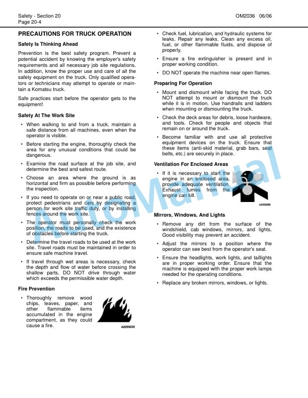
Komatsu 730E Dump Truck Operation and Maintenance Manual CEAM018100
Komatsu Operation and Maintenance Manual PDF
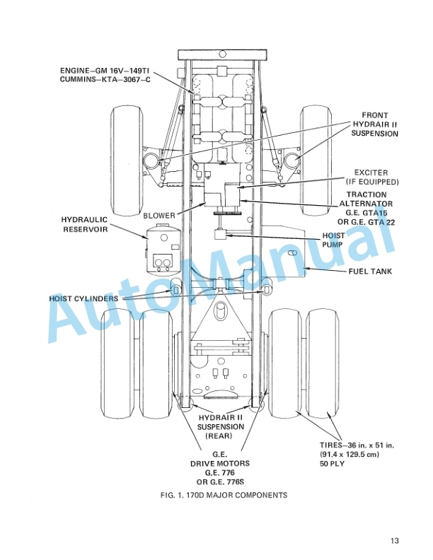
Komatsu 170D Dump Truck Operation and Maintenance Manual DG534
Komatsu Operation and Maintenance Manual PDF
Komatsu 430FX-1, 430FXL-1, 445FXL-1 Operation and Maintenance Manual CEAM023702
Komatsu Operation and Maintenance Manual PDF
Komatsu 330M Dump Truck Operation and Maintenance Manual DG729
Komatsu Operation and Maintenance Manual PDF
Komatsu 210M Dump Truck Operation and Maintenance Manual DG714