Komatsu PC600-8, PC600LC-8 Field Assembly Instruction GEN00043-04
$20.00
- Type Of Manual: Field Assembly Instruction
- Manual ID: GEN00043-04
- Format: PDF
- Size: 12.9MB
- Number of Pages: 138
-
Model List:
- PC600-8
- PC600LC-8
- 1. COVER
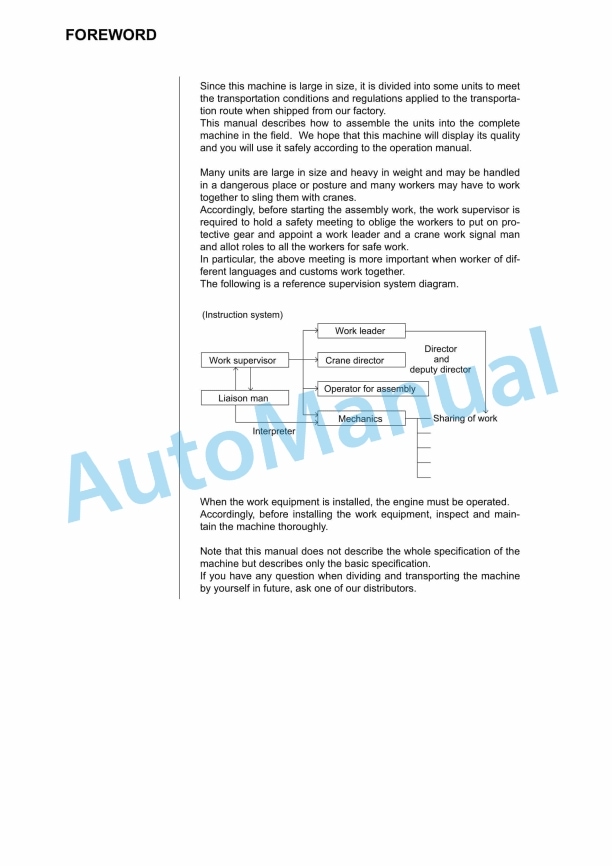
- 2. FOREWORD
- 3. CONTENTS
- 4. SPECIFICATIONS
- 5. PRECAUTIONS FOR FIELD ASSEMBLY
- 6. DISPOSAL OF REMOVED PARTS
- 7. ASSEMBLING PROCEDURES, APPLICABLE EQUIPMENT AND SCHEDULE
- 8. KIT LAYOUT DIAGRAM
- 9. TRANSPORTATION
- 10. LIST OF TOOLS FOR FIELD ASSEMBLING
- 11. TIGHTENING TORQUE
- 12. ASSEMBLY OF CHASSIS
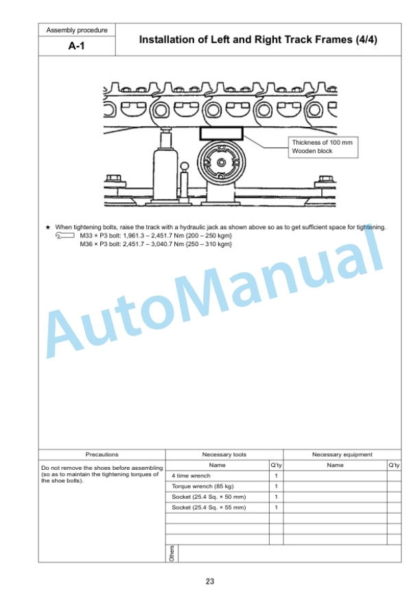
- 12.1. A1. Installation of Left and Right Track Frames
- 12.2. A2. Installation of Travel Pipe
- 12.3. A3. Installation of Operator Cabs Left Handrail
- 12.4. A4. Installation of Operator Cabs Door Stopper and Striker
- 12.5. A5. Installation of Rearview Mirror
- 12.6. A6. Installation of Handrail
- 12.7. A7. Installation of Step
- 12.8. A8. Installation of Left Side Step
- 12.9. A9. Sticking Sheet to Counterweight
- 12.10. A10. Installation of Counterweight
- 12.11. A11. Installation of Step Light
- 12.12. A12. Installation of Travel Piping Cover
- 12.13. A13. Testing Track Shoe Tension
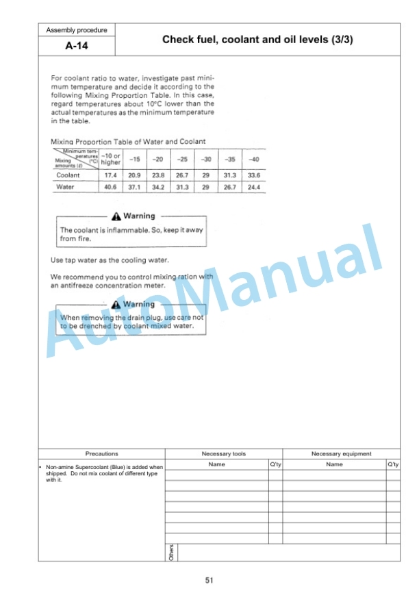
- 12.14. A14. Check Fuel, Coolant and Oil Levels
- 13. ASSEMBLING OF WORK EQUIPMENT
- 13.1. B1. Assembly of Arm Cylinder
- 13.2. B2. Connection of Arm Cylinder Hoses
- 13.3. B3. Installation of Boom Cylinder
- 13.4. B4. Installation of Boom Foot Dust Seal
- 13.5. B5. Assembly of Boom Assembly
- 13.6. B6. Installation of Boom Cylinder Hoses
- 13.7. B7. Installation of Hoses from Chassis Along Top of Boom
- 13.8. B8. Connection of Boom Cylinder Head
- 13.9. B9. Installation of Arm Assembly
- 13.10. B10. Installation of Bucket Cylinder Hoses between Boom and Bucket Cylinder
- 13.11. B11. Installation of Bucket
- 13.12. B12. Connection of Work Equipment Grease Piping
- 13.13. B13. Connection of Work Equipment Wiring
- 13.14. B14. Greasing after Assembling Work Equipment
- 13.15. B15. Bleeding Air from Work Equipment Circuit
- 13.16. B16. Parts to be Touched up After Field Assembly
- 14. PROCEDURE FOR INSPECTION AND MAINTENANCE AFTER COMPLETION OF ASSEMBLY
- 14.1. M1. Inspection of Oil Level in Hydraulic Tank and Refill
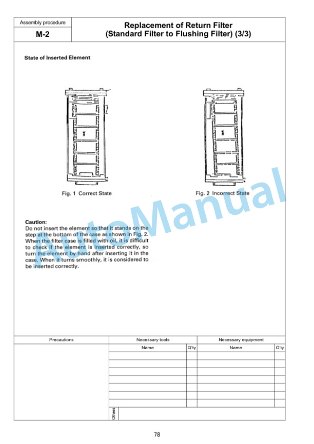
- 14.2. M2. Replacement of Return Filter (Standard Filter to Flushing Filter)
- 14.3. M3. Flushing of Hydraulic Circuit
- 14.4. M4. Error Code
- 14.5. M5. Operating Method of Monitoring
- 15. ASSEMBLING OF COUNTERWEIGHT REMOVER
- 15.1. D1. Sticking Sheet to Counterweight
- 15.2. D2. Adjustment of Shims for Counterweight
- 15.3. D3. Greasing
- 15.4. D4. Installation of Counterweight Remover
- 15.5. D5. Installation of Covers
- 15.6. D6. Installation of Clamps
- 15.7. D7. Installation of Hoses
- 15.8. D8. Bleeding Air from Counterweight Remover Circuit
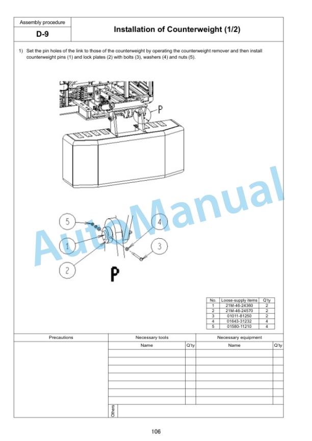
- 15.9. D9. Installation of Counterweight
- 15.10. D10. Check of Operation
- 16. Field Assembly Inspection Report (Backhoe)
Komatsu Operation and Maintenance Manual PDF
Komatsu 730E Dump Truck Operation and Maintenance Manual CEAM006700
Komatsu Operation and Maintenance Manual PDF
Komatsu Operation and Maintenance Manual PDF
Komatsu 150A, 150FA Crane Operation and Maintenance Manual CEAMC20081
Komatsu Operation and Maintenance Manual PDF
Komatsu 730E Dump Truck Operation and Maintenance Manual CEAM011200
Komatsu Operation and Maintenance Manual PDF
Komatsu 530M Dump Truck Operation and Maintenance Manual DG716
Komatsu Operation and Maintenance Manual PDF
Komatsu 730E Dump Truck Operation and Maintenance Manual CEAM010301
Komatsu Operation and Maintenance Manual PDF
Komatsu 730E Dump Truck Operation and Maintenance Manual CEAM018100
Komatsu Operation and Maintenance Manual PDF
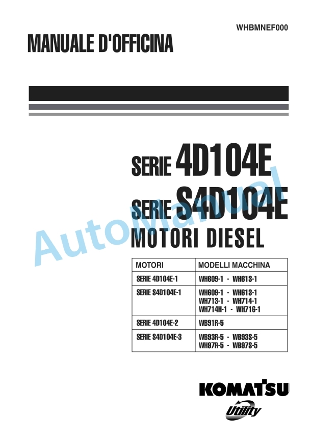
Komatsu 4D104E, S4D104E Series Diesel Motor Operation and Maintenance Manual WHBMNEF000
Komatsu Operation and Maintenance Manual PDF
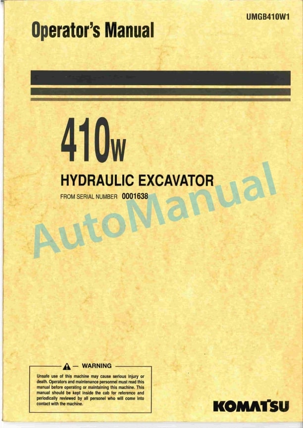
Komatsu 410W Hydraulic Excavator Operation and Maintenance Manual UMGB410W1
Komatsu Operation and Maintenance Manual PDF
Komatsu 210M Dump Truck Operation and Maintenance Manual DG714

