Komatsu D375A-8E0 Bull Dozer Field Assembly Instruction GEN00200-00
$20.00
- Type Of Manual: Field Assembly Instruction
- Manual ID: GEN00200-00
- Format: PDF
- Size: 16.9MB
- Number of Pages: 242
-
Model List:
- D375A-8E0 Bull Dozer
- 1. Cover
- 2. Preface
- 3. CONTENTS
- 4. Specifications
- 5. Precautions for field assembly
- 6. Disposal of removed parts
- 7. Assembly procedure, necessary equipment, and schedule
- 8. Layout of kit
- 9. Style for transportation
- 10. Table of tools for field assembly
- 11. Tightening torque
- 12. Coating materials list
- 13. Selection of wire ropes used for assembly
- 14. Assembly
- 14.1. A1 Installation of chassis
- 14.2. A2 Installation of final drive assy
- 14.3. A3 Installation of undercarriage
- 14.4. A4 Adding oil to recoil chamber and pivot chamber
- 14.5. A5 Installing direction of exhaust pipe
- 14.6. A6 Installation of blade lift cylinder
- 14.7. A7 Installation of cylinder yoke grease hose
- 14.8. A8 Installation of ripper
- 14.9. A9 Installation of grease hose of ripper pin
- 14.10. A10 Installation of track
- 14.11. A11 Assembly of blade
- 14.12. A12 Installation of blade
- 14.13. A13 Installation of KOMTRAX antenna
- 14.14. A14 Installation of ROPS guard
- 14.15. A15 Installation of platform
- 14.16. A16 Installation of AUX BOX
- 14.17. A17 Check track tension
- 14.18. A18 Check fuel, coolant and lubricants
- 14.19. A19 Bleeding air from hydraulic cylinders
- 14.20. A20 Lubricating
- 14.21. A21 Installation of fuel quick charge piping
- 14.22. A22 Installation of ladder
- 15. Check and maintenance procedures after completion of assembly
- 15.1. M1 Inspection of machine monitor
- 15.2. M2 Setting procedure for USER ADJUST MODE
- 15.3. M3 Replacement of return filter
- 15.4. M4 Flushing of hydraulic circuit, and bleeding air from hydraulic cylinders
- 15.5. M5 Replacement of return filter
- 15.6. M6 Bleeding air from hydraulic cylinders
- 15.7. M7 Method for starting up KOMTRAX terminal and default setting of KOMTRAX Plus controller etc
- 16. CALIBRATION OF CUTTING EDGE
- 16.1. Operations and checks after starting engine
- 16.2. Procedure 1. Adjustment ID 8041 (iB MACHINE SPEC SET MODE)
- 16.3. Procedure 2. Resetting of cylinder stroke end
- 16.4. Procedure 3. Adjustment ID 8043 (Adjustment of installed lengths of R.H. and L.H. lift cylinders)
- 16.5. Procedure 4. Adjustment ID 8044 (L.H. tilt cylinder automatic adjustment)
- 16.6. Procedure 5. Adjustment ID 8048 (AUTO PITCH ADJUST)
- 16.7. Procedure 6. Adjustment ID 8040 (CYLINDER CALIBRATION MODE)
- 16.8. Procedure 7. Adjustment ID 8042 (iB W/E VALVE AUTO SET MODE)
- 16.9. Procedure 8. Inputting wear amount of blade edge and track shoe
- 16.10. Procedure 9. 10. Special functions of control box
- 16.11. Procedure 9. Operation of Machine Cal Step A menu
- 16.12. Procedure 10. Operation of Machine Cal Step B menu
- 16.13. Procedure 11. Checking and adjusting blade edge elevation
- 17. Field assembly inspection report
Komatsu Operation and Maintenance Manual PDF
Komatsu 503 Motor Grader Operation and Maintenance Manual 2079A-H45
Komatsu Operation and Maintenance Manual PDF
Komatsu 730E Dump Truck Operation and Maintenance Manual CEAM011200
Komatsu Operation and Maintenance Manual PDF
Komatsu 210M Dump Truck Operation and Maintenance Manual DG615
Komatsu Operation and Maintenance Manual PDF
Komatsu 430FX-1, 430FXL-1, 445FXL-1 Operation and Maintenance Manual CEAM023702
Komatsu Operation and Maintenance Manual PDF
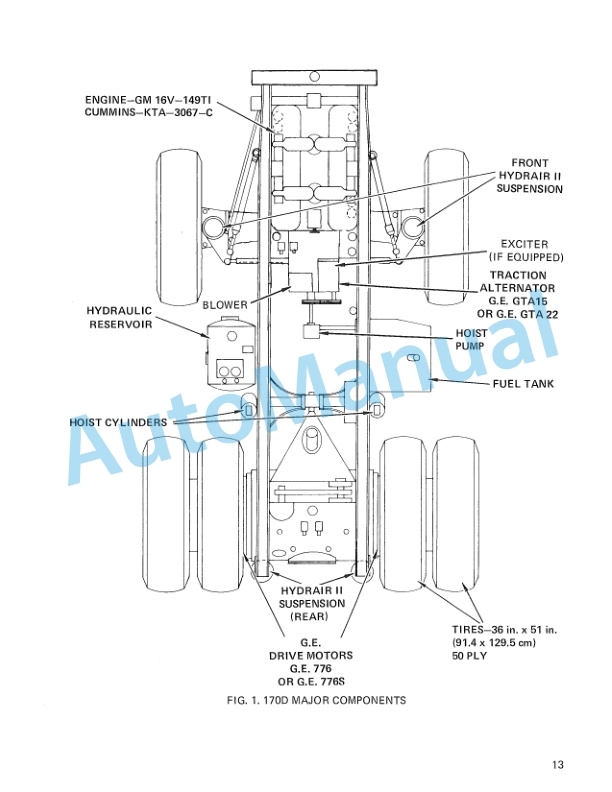
Komatsu 170D Dump Truck Operation and Maintenance Manual DG534
Komatsu Operation and Maintenance Manual PDF
Komatsu 210M Dump Truck Operation and Maintenance Manual DG692
Komatsu Operation and Maintenance Manual PDF
Komatsu 4D104E, S4D104E Series Diesel Motor Operation and Maintenance Manual WHBMNEF000
Komatsu Operation and Maintenance Manual PDF
Komatsu 630E Dump Truck Operation and Maintenance Manual DG738
Komatsu Operation and Maintenance Manual PDF
Komatsu 210M Dump Truck Operation and Maintenance Manual DG725