


Komatsu Operation and Maintenance Manual PDF
Komatsu 210M Dump Truck Operation and Maintenance Manual DG725
Komatsu Operation and Maintenance Manual PDF
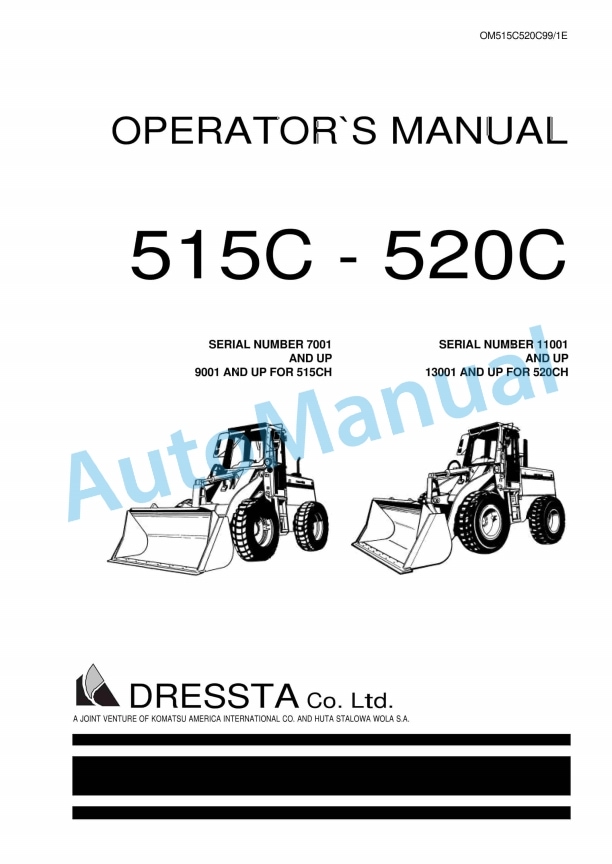
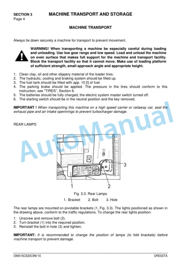
Komatsu 515C, 520C Operation and Maintenance Manual OM515C520C99-1E
Komatsu Operation and Maintenance Manual PDF
Komatsu 503 Motor Grader Operation and Maintenance Manual 2079A-H45
Komatsu Operation and Maintenance Manual PDF
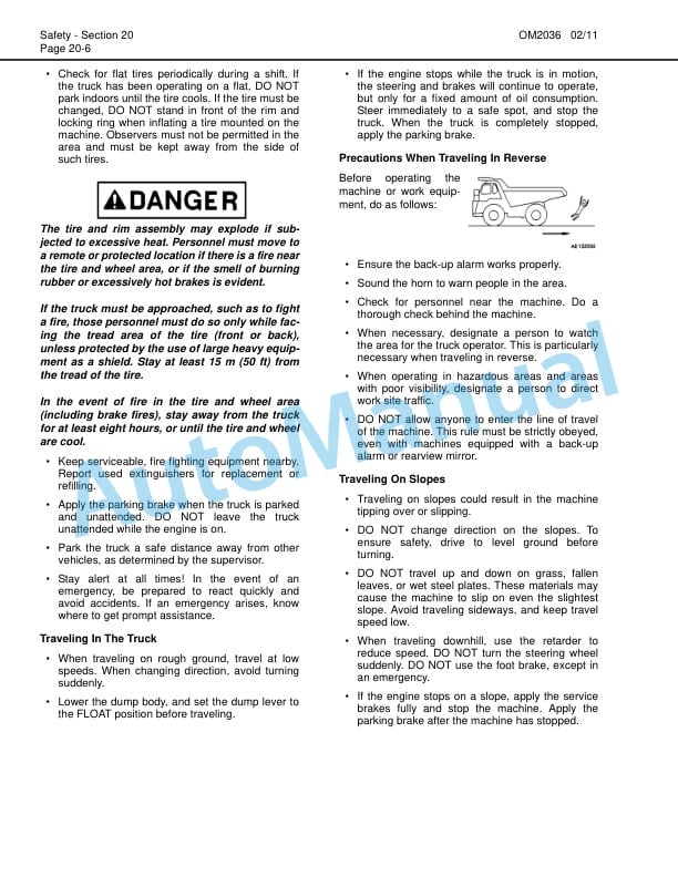
Komatsu 730E Dump Truck Operation and Maintenance Manual CEAM020001
Komatsu Operation and Maintenance Manual PDF
Komatsu 330M Dump Truck Operation and Maintenance Manual DG729
Komatsu Operation and Maintenance Manual PDF
Komatsu 730E Dump Truck Field Assembly Instruction CEAW004103
Komatsu Operation and Maintenance Manual PDF
Komatsu 730E Dump Truck Operation and Maintenance Manual CEAM011200
Komatsu Operation and Maintenance Manual PDF
Komatsu 330M Dump Truck Operation and Maintenance Manual DG713
Komatsu Operation and Maintenance Manual PDF
Komatsu 730E Dump Truck Operation and Maintenance Manual CEAM013300